Page 29 - Shimadzu Dynamic and Fatigue Testing Systems
P. 29

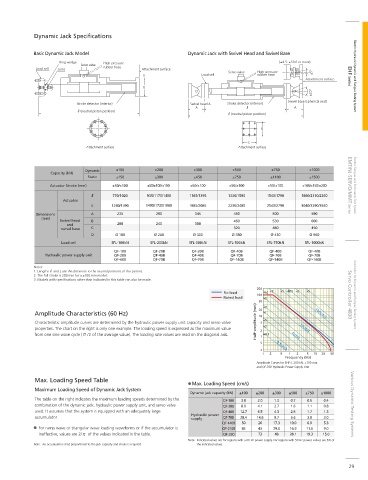
Dynamic Jack Speci cations

            Basic Dynamic Jack Model                           Dynamic Jack with Swivel Head and Swivel Base
                     Ring wedge    High-pressure                                             (±4.5: ±50tf or more)
                            Servo valve
             Load cell  Joint      rubber hose  Attachment surface
                                                                             Servo valve  High-pressure  ±5°
                                                 E                  Load cell         rubber hose                   EHF Series  Electric Hydraulic Dynamic and Fatigue Testing System
                                                                                                      Attachment surface
                                                D
                                                                                                        ±20°
                                                                                                Swivel base (spherical seat)
                          Stroke detector (interior)            Swivel head A  Stroke detector (interior)
                                                                  A                               A
                            (neutral piston position)
                                                                              (neutral piston position)
                                                                                        B

                                                                                   C
                              Attachment surface                                Attachment surface


                             Dynamic   ±100         ±200         ±300         ±500         ±750        ±1000
                  Capacity (kN)
                              Static   ±150         ±300         ±450         ±750         ±1100       ±1500
                  Actuator Stroke (mm)  ±50/±100  ±50/±100/±150  ±50/±100    ±50/±100     ±50/±100   ±100/±150/±200  EMT/NJ-SERVO/MMT Series  Electric Fatigue and Endurance Test System
                                      770/1020    935/1170/1400  1165/1395   1330/1580   1540/1790   1860/2110/2360
                      Actuator
                               L      1240/1490  1495/1730/1960  1885/2085   2230/2480   2540/2790   3040/3290/3540
             Dimensions        A        235          280          345         450          500          590
               (mm)
                     Swivel head   B                                          460          530          600
                       and              200          240          300
                     swivel base  C                                           320          440          450
                               D       Ø 180        Ø 240        Ø 300        Ø 380        Ø 430        Ø 560
                     Load cell        SFL-100kN    SFL-200kN    SFL-300kN    SFL-500kN   SFL-750kN    SFL-1000kN
                                       QF-10B       QF-20B       QF-20B      QF-40B       QF-40B       QF-40B
                Hydraulic power supply unit  QF-20B  QF-40B      QF-40B      QF-70B       QF-70B       QF-70B
                                       QF-40B       QF-70B       QF-70B      QF-140B      QF-140B      QF-140B
            Notes:
            1. Lengths     and L are the distances to the neutral positions of the pistons.
            2. The full stroke is 200 mm for a ±100 mm model.
            3. Models with speci cations other than indicated in this table can also be made.
                                                                                      200
                                                                           No load    100  +10  +2  +5 +100 +2  +5    Controller for Dynamic and Fatigue Testing Systems
                                                                           Rated load   +5                          Servo Controller 4830
                                                                                       50
             Amplitude Characteristics (60 Hz)                                         20  +2            100cm/s
                                                                                        +1
                                                                                       10
             Characteristic amplitude curves are determined by the hydraulic power supply unit capacity and servo valve   Half-amplitude (mm)  5  +5
             properties. The chart on the right is only one example. The loading speed is expressed as the maximum value   2  +2  10cm/s
             from one sine wave cycle (     /2 of the average value). The loading rate values are read on the diagonal axis.  1  +0.1  1cm/s
                                                                                       5     0.1cm/s
                                                                                       2
                                                                                        1  2  5  1  2  5  10  20  50
                                                                                               Frequency (Hz)
                                                                                      Amplitude Curves for EHF-J, 200 kN, ±100 mm,
                                                                                      and QF-70B Hydraulic Power Supply Unit
             Max. Loading Speed Table
                                                                 Max. Loading Speed (cm/s)
             Maximum Loading Speed of Dynamic Jack System
                                                                Dynamic jack capacity (kN)  ±100  ±200  ±300  ±500  ±750  ±1000
             The table on the right indicates the maximum loading speeds determined by the   QF-10B  3.8  2.0  1.3  0.7  0.5  0.4
             combination of the dynamic jack, hydraulic power supply unit, and servo valve   QF-20B  8.0  4.1  2.7  1.6  1.1  0.8  Various Dynamic Testing Systems
             used. It assumes that the system is equipped with an adequately large   QF-40B  12.7  6.5  4.3  2.5  1.7  1.3
             accumulator.                                       Hydraulic power  QF-70B  28.4  14.6  9.7  5.6  3.8  3.0
                                                                supply
                                                                           QF-140B  50  26  17.3  10.0  6.9  5.3
              For ramp wave or triangular wave loading waveforms or if the accumulator is   QF-210B  85  43  29.0  16.9  11.6  9.0
              ineffective, values are 2/     of the values indicated in the table.  QF-330  73  48  28.1  19.3  15.0
                                                               Note:  Indicated values are for regions with a 60 Hz power supply. For regions with 50 Hz power, values are 5/6 of
            Note:  An accumulator sized proportional to the jack capacity and stroke is required.  the indicated values.


                                                                                                                     29
   24   25   26   27   28   29   30   31   32   33   34