
Page 27 - Shimadzu Dynamic and Fatigue Testing Systems
P. 27
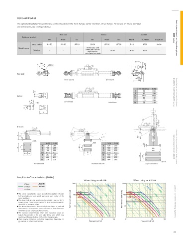
Optional Bracket
            The optional brackets indicated below can be installed on the front  ange, center trunnion, or tail  ange. For details on where to install
            and dimensions, see the  gure below.

                                         Rod end                    Swivel                     Bracket
                Optional bracket                                                                                    EHF Series  Electric Hydraulic Dynamic and Fatigue Testing System
                                 Set      Front    Tail       Set      Front   Tail    Front   Trunnion  Angle set
                      ±5 to 20 kN  JRS-20  JRF-20  JRT-20    JSS-20    JSF-20  JST-20  JF-20    JT-20    JA-20
             Model name                                    If the base and
                       30/50kN    -        -        -     head are used in   JS-50     JF-50    JT-50      -
                                                           combination,
                                                          purchase two sets.


            Rod End

                                            Front rod end              Tail rod end

                                                                                             JSF-20,JST-20  JS-50
                                                                                           A    60     200
                                                                                           B    60     200          EMT/NJ-SERVO/MMT Series  Electric Fatigue and Endurance Test System
            Swivel                                                                        Ød    Ø11   Ø22
                                                                                           H    80     140
                                                                                           L    135    200
                                            Swivel head
                                                                         Swivel base      W     78     140


            Bracket


                               JF-20  JF-50                             JT-20  JT-50
                             A  120  200                              A  120  200
                             B  160  200                              B  160  200                                   Servo Controller 4830  Controller for Dynamic and Fatigue Testing Systems
                             C  160  200                              C  160  200
                            Ød  Ø18  Ø22                             Ød  Ø18  Ø22
                             H  202  265                             H   190  240
                             L  200  255                              L  200  250
                             W  230  270                             W   184  280
                       Front bracket                          Trunnion bracket                    Angle set bracket


            Amplitude Characteristics (60 Hz)
                                                         When Using an AF-10B             When Using an AF-20B
                 JF5kN     JF30kN                1000                              1000
                 JF10kN    JF50kN                                       10000cm/s                        10000cm/s
                 JF20kN                              ±150        1000cm/s  1000G       ±150       1000cm/s  1000G
             The above characteristic curves indicate the relation between   100  ±100  100cm/s  100  ±100  100cm/s
             half-amplitude and cycle speed, given sine wave motion at the   ±50  100G  ±50             100G
             rated load level.                          10cm/s     10G                   10cm/s      10G
             The above indicates the amplitude characteristics given a 60 Hz   Half-amplitude (mm)  1G  Half-amplitude (mm)  1G
             power supply. Characteristics with a 50 Hz power supply will be   0.1G       0.01G  0.1G                Various Dynamic Testing Systems
             about 5/6 of indicated values.         1cm/s  0.01G                      1cm/s
             The above characteristics do not include the frame or load cell   10   10
             characteristics. Compensate for the in uence of these factors to
             determine actual amplitude characteristics.
             The indicated characteristics values were calculated based on
             typical  characteristics of  the servo valve  being  used, which may
             result in a difference of about 10 % on the frequency axis.  1         1
             There may be limitations on testing frequencies, depending on   0.1  1  10  100  0.1  1  10      100
             jig, sample, or other characteristics.         Frequency (Hz)                     Frequency (Hz)

                                                                                                                     27