Page 26 - Shimadzu Dynamic and Fatigue Testing Systems
P. 26

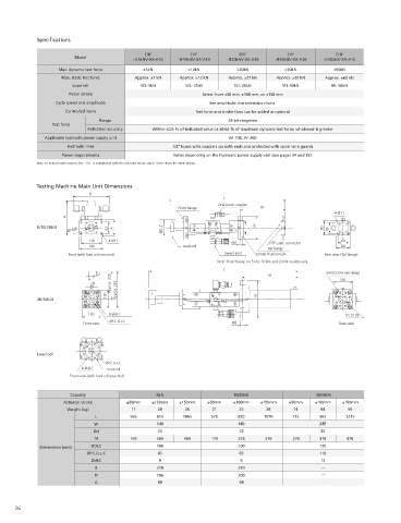
Specifications                                                                                                            Optional Bracket
                                                                                                                                      The optional brackets indicated below can be installed on the front flange, center trunnion, or tail flange. For details on where to install
                                             EHF           EHF            EHF           EHF            EHF
                        Model
                                          -JF5kNV-XX-A10  -JF10kNV-XX-A10  -JF20kNV-XX-A10  -JF30kNV-XX-A10  -JF50kNV-XX-A10          and dimensions, see the figure below.
                   Max. dynamic test force   ±5kN         ±10kN          ±20kN          ±30kN         ±50kN
                    Max. static test force  Approx. ±7 kN  Approx. ±13 kN  Approx. ±27 kN  Approx. ±39 kN  Approx. ±63 kN                                          Rod end                    Swivel                     Bracket
                                                                                                                                          Optional bracket
                       Load cell            SCL-5kN      SCL-10kN       SCL-20kN       SFL-30kN       SFL-50kN                                             Set      Front    Tail       Set      Front   Tail    Front   Trunnion  Angle set  EHF Series  Electric Hydraulic Dynamic and Fatigue Testing System
                      Piston stroke                            Select from ±50 mm, ±100 mm, or ±150 mm
                                                                                                                                                ±5 to 20 kN  JRS-20  JRF-20  JRT-20    JSS-20   JSF-20  JST-20   JF-20    JT-20    JA-20
                  Cycle speed and amplitude                      See amplitude characteristics charts.
                                                                                                                                       Model name                                    If the base and
                     Controlled items                       Test force and stroke (two can be added as options)                                  30/50kN    -        -        -     head are used in   JS-50     JF-50    JT-50      -
                                                                                                                                                                                     combination,
                                                                                                                                                                                    purchase two sets.
                               Range                                  24-bit rangeless
                 Test force
                            Indication accuracy  Within ±0.5 % of indicated value or ±0.02 % of maximum dynamic test force, whichever is greater
               Applicable hydraulic power supply unit                  AF-10B, AF-20B
                     Hydraulic lines                 1/2" hoses with couplers on both ends and protected with spiral wire guards
                    Power requirements                Varies depending on the hydraulic power supply unit (see pages 34 and 35).
            Note: In actual model names, the "XX" is substituted with the actuator stroke value. Select from the table below.         Rod End
                                                                                                                                                                      Front rod end              Tail rod end
            Testing Machine Main Unit Dimensions
                            B                                                                                                                                                                                          JSF-20,JST-20  JS-50
                                                                     L                                                                                                                                               A    60    200
                                                                   One-touch coupler                                                                                                                                 B    60    200           EMT/NJ-SERVO/MMT Series  Electric Hydraulic Dynamic and Fatigue Testing System
                                                       Front flange             TR                                                    Swivel                                                                        Ød    Ø11   Ø22
                                                                                                       4-Ø11                                                                                                         H    80    140
                     H                                                                                                                                                                                               L    135   200
                                                                                                                                                                      Swivel head                  Swivel base
            5/10/20kN                                                          W                   80                                                                                                               W     78    140
                      Ø74g6       62  A           ØDLC                                               60
                            118   4-Ø11                                Ød          DTF cable connector   60
                            140                          Load cell                                       80
                                                                                  Tail flange
                      Front (with load cell removed)                 Swivel joint  Center trunnion pin  Rear view (Tail flange)
                                                                   Note: Front flange on 5 kN, 10 kN, and 20 kN models only.
                                                                     L
                                                                                                    8-M12 (24 mm deep)                Bracket
                                                                                  TR
                                   Approx. 200                                                          130
                                 130  Approx. 265                              W
            30/50kN
                            130   8-ØdLC                                                                  P.C.D.95                                       JF-20  JF-50                             JT-20  JT-50
                                  ØP.C.D.LC                                                                                                            A  120  200                             A  120  200                                      Controller for Dynamic and Fatigue Testing Systems
                          Front view                                    Ød                              Rear view                                      B  160  200                             B  160  200                                    Servo Controller 4830
                                                                                                                                                       C  160  200                             C  160  200
                                                                                                                                                      Ød  Ø18  Ø22                             Ød  Ø18  Ø22
                                                                                                                                                       H  202  265                             H  190  240
                                                                                                                                                       L  200  255                             L  200  250
                                                                                                                                                      W   230  270                             W  184  280
            Load cell
                                                                                                                                                 Front bracket                          Trunnion bracket                    Angle set bracket
                                 ØP.C.D.LC
                          8-ØdLC  Load cell
                      Front view (with load cell attached)
                                                                                                                                      Amplitude Characteristics (60 Hz)
                      Capacity                   5kN                    10/20kN                  30/50kN                                                                           When Using an AF-10B             When Using an AF-20B
                    Actuator stroke    ±50mm   ±100mm   ±150mm  ±50mm   ±100mm  ±150mm   ±50mm   ±100mm  ±150mm                            JF5kN     JF30kN                1000                             1000
                     Weight (kg)         17      20      26       21      25      28      74       84      94                              JF10kN    JF50kN                                1000cm/s  10000cm/s              1000cm/s  10000cm/s
                                                                                                                                           JF20kN
                              L          565     815     1065    570     820     1070     715     965     1215                                                                 ±150                1000G        ±150                 1000G
                              W                  140                     140                      245                                  The above characteristic curves indicate the relation between   100  ±100  100cm/s  100  ±100  100cm/s
                                                                                                                                       half-amplitude and cycle speed, given sine wave motion at the   100G                       100G
                             Ød                  25                       25                      30                                                                           ±50           10G                ±50            10G
                                                                                                                                       rated load level.                          10cm/s                           10cm/s
                              TR         169     269     369     176     276      376     278     378     478                          The above indicates the amplitude characteristics given a 60 Hz   Half-amplitude (mm)  0.1G  1G  Half-amplitude (mm)  0.1G  1G  Various Dynamic Testing Systems
                                                                                                                                       power supply. Characteristics with a 50 Hz power supply will be              0.01G
             Dimensions (mm)  ØDLC               100                     100                      125                                  about 5/6 of indicated values.         1cm/s  0.01G                      1cm/s
                           ØP.C.D.L.C            85                       85                      110                                  The above characteristics do not include the frame or load cell   10   10
                                                                                                                                       characteristics. Compensate for the influence of these factors to
                             ØdLC                9                        9                       13                                   determine actual amplitude characteristics.
                              B                  210                     210                                                           The indicated characteristics values were calculated based on
                                                                                                                                       typical  characteristics of  the servo valve  being  used, which may
                              H                  196                     200                                                           result in a difference of about 10 % on the frequency axis.  1         1
                                                                                                                                       There may be limitations on testing frequencies, depending on   0.1  1  10  100  0.1  1  10      100
                              A                  80                       84
                                                                                                                                       jig, sample, or other characteristics.         Frequency (Hz)                     Frequency (Hz)
      26                                                                                                                                                                                                                                      27
   21   22   23   24   25   26   27   28   29   30   31