
Page 21 - Shimadzu Dynamic and Fatigue Testing Systems
P. 21
Specifications C D
E B
2566 EHF Series Electric Hydraulic Dynamic and Fatigue Testing System
A
786
904 825
With Table Housing AF-4 Hydraulic Power Supply Unit
EHF EHF EHF EHF EHF EHF
Model
-LV005k1A -LV005k2A -LV010k1A -LV010k2A -LV020k1A -LV020k2A
Max. dynamic test force ±5kN ±10kN ±20kN
Max. static test force ±6kN ±12kN ±24kN
±25mm ±50mm ±25mm ±50mm ±25mm ±50mm
Piston stroke
Units with a maximum stroke of ±100 mm can also be made.
Cycle speed and amplitude See amplitude characteristics charts.
Controlled items Test force and stroke (two can be added as options)
Range 24-bit rangeless
Test force
Indication accuracy Within 0.5 % of indicated value or ±0.02 % of maximum dynamic test force, whichever is greater
Crosshead drive mechanism Hydraulic drive (with hydraulic clamp)
Applicable hydraulic power supply unit AF-4, AF-10B, AF-20B, QF-10B, QF-20B EMT/NJ-SERVO/MMT Series Electric Fatigue and Endurance Test System
Power requirements Varies depending on the hydraulic power supply unit (see pages 34 and 35).
Testing space A 140 to 830 115 to 805 140 to 830 115 to 805 140 to 830 115 to 805
(mm) B 460
C 800
Main unit
dimensions (mm) D 600
E 1760 1770 1760 1770 1760 1770
Weight (kg) 360 370 365 375 370 380
Frame rigidity (mm/kN) 0.0033 (given a 500 mm crosshead-table clearance)
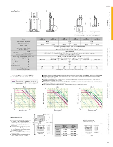
Amplitude Characteristics (60 Hz) The above characteristic curves indicate the relation between half-amplitude and cycle speed, given sine wave motion at the rated load level.
The above indicates the amplitude characteristics given a 60 Hz power supply. Characteristics with a 50 Hz power supply will be
about 5/6 of indicated values.
The above characteristics do not include the frame or load cell characteristics. Compensate for the in uence of these factors to
AF-4 determine actual amplitude characteristics.
QF-10B/AF-10B 25 mm stroke The indicated characteristics values were calculated based on typical characteristics of the servo valve being used, which may result
QF-20B/AF-20B 50 mm stroke in a difference of about 10 % on the frequency axis.
There may be limitations on testing frequencies, depending on jig, sample, or other characteristics.
5kN 10kN 20kN
100 100cm/s 100G 100 100cm/s 100G 100 1G 100cm/s 100G Servo Controller 4830 Controller for Dynamic and Fatigue Testing Systems
Half-amplitude (mm) 10 1 0.1cm/s 0.01G 0.1G 10cm/s 10G Half-amplitude (mm) 10 1 0.1cm/s 0.01G 10cm/s 0.1G 10G Half-amplitude (mm) 10 1 0.1cm/s 0.01G 0.1G 10cm/s 10G
1G
1G
1cm/s
1cm/s
1cm/s
0.1 0.1 0.1
0.1 1 10 0.1 1 10 0.1 1 10
Frequency (Hz) Frequency (Hz) Frequency (Hz)
Power supply
Hydraulic
Standard Layout power supply
Cooling unit
water
At the installation site, provide about 500 mm With Table Housing AF-4
of space on all four sides of the system, in High-pressure Hydraulic Power Supply Unit
addition to the space requirements indicated rubber hose Electrical wiring
above, to allow access for operation and Various Dynamic Testing Systems
maintenance. Hydraulic Space
The drawing above indicates the dedicated Main unit power required
space requirements. The shape and orientation supply unit (W x D)
of the hydraulic power supply unit may vary L5kN QF-10B 2000×2200
depending on its capacity.
For a more detailed standard layout drawing, Testing machine L10kN QF-20B 2000×2400 Testing machine Controller
contact Shimadzu. main unit Controller AF-10B 2000×2400 main unit
The standard system con guration does not L20kN
include the table, computer, or printer. AF-20B 2000×2400
21