Page 16 - Shimadzu Dynamic and Fatigue Testing Systems
P. 16

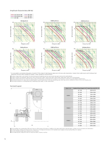
Amplitude Characteristics (60 Hz)
                                                                                                                                      Electric-Hydraulic Dynamic and Fatigue Testing System
                 QF-10B/AF-10B  QF-70B*                                                                                               EHF-U Series
                 QF-20B/AF-20B  QF-110 *
                 QF-40B         QF-140*
                                                                                                                                                                                                                             Civil Engineering,
                                                                                                                                                                                                              Automobiles  Steel, Metals, Machines  Construction  R&D
                        50kN±25mm                        100kN±25mm                        200kN±25mm
               100                               100                              100                                                 For Full-Scale Fatigue and Endurance Testing of                                                         EHF Series  Electric Hydraulic Dynamic and Fatigue Testing System
                                                                                                                                      Structural Materials and Large Samples
                                                               1G
                            1G
                                                                                         10cm/s
                                    100G
             Half-amplitude (mm)  10 1  0.01G  0.1G  10cm/s  Half-amplitude (mm)  10 1  0.01G  0.1G  10cm/s  Half-amplitude (mm)  10 1  0.01G  0.1G  By providing a T-slot surface plate at the bottom of a U-type loading frame with a top-mounted actuator, these systems allow installation of extra
                                                                       100G
                                                                                                         100G
                                                                                                 1G
                              100cm/s 10G
                                                                                                   100cm/s 10G
                                                                 100cm/s 10G
                                                                                                                                      large components and parts. Due to the large testing space, dynamic testing and evaluation can be performed on a variety of samples, including
                                                                                                                                      full-size samples and structural members.
                          1cm/s
                                                             1cm/s
               0.1   0.1cm/s                     0.1    0.1cm/s                    0.1   0.1cm/s  1cm/s                                    Rated Actuator Capacities of
                0.1      1      10                0.1      1       10               0.1      1      10
                        Frequency (Hz)                     Frequency (Hz)                    Frequency (Hz)                                50 kN, 100 kN, and 200 kN Support
                                                                                                                                           a Wide Range of Dynamic Testing
                        50kN±50mm                        100kN±50mm                         200kN±50mm
              100             100cm/s 10G  100G  100          1G  100cm/s 10G  100G  100         1G  100cm/s 10G  100G
             Half-amplitude (mm)  10  0.01G  0.1G  10cm/s 1G  Half-amplitude (mm)  10  0.01G  0.1G  10cm/s  Half-amplitude (mm)  10  0.01G  10cm/s  Top-Mounted Actuator                   Hydraulically                                      EMT/NJ-SERVO/MMT Series  Electric Hydraulic Dynamic and Fatigue Testing System
                                                                                                                                      Supports dynamic and endurance testing of full-size samples, large components,
                                                                                                                                      and structural members.
                                                                                                                                                                                           lifting/lowering crosshead
                                                                                                 0.1G
                                                  1
                                                                                    1
                1
                          1cm/s
                                                                                              1cm/s
                                                            1cm/s
                                                                                                                                      ±0.5 % test force accuracy
                                                                                         0.1cm/s
                     0.1cm/s
                                                       0.1cm/s
               0.1                               0.1                               0.1                                                Test force accuracy is guaranteed to within ±0.5 % of the indicated value.
                0.1      1      10                0.1      1       10               0.1      1       10
                        Frequency (Hz)                     Frequency (Hz)                    Frequency (Hz)
            * It is not possible to use standard configurations of models QF-70B or higher for high-frequency regions due to the servo valve characteristics. However, these models may be used for testing at high
             frequencies if the servo valve is changed, for example. Contact Shimadzu for more information.
             The above characteristic curves indicate the relation between half-amplitude and cycle speed, given sine wave motion at the rated load level.
             The above indicates the amplitude characteristics given a 60 Hz power supply. Characteristics with a 50 Hz power supply will be about 5/6 of indicated values.
             The above characteristics do not include the frame or load cell characteristics. Compensate for the influence of these factors to determine actual amplitude characteristics.
             The indicated characteristics values were calculated based on typical characteristics of the servo valve being used, which may result in a difference of about 10 % on the frequency axis.
             There may be limitations on testing frequencies, depending on jig, sample, or other characteristics.
                                                                                                                                           High Rigidity and Large Testing Space
            Standard Layout
                                                                                                                                      A T-slot surface plate makes it easy to secure samples.
                                                                          Main Unit  Hydraulic Power Supply Unit Space Required (W x D)                                                                                                       Servo Controller 4830  Controller for Dynamic and Fatigue Testing Systems
                                                                                                                                      The size of the surface plate and length of the columns can be customized       High-accuracy column
                                                                                        QF-10B       2300×2100
                                                                                                                                      based on the size of samples.
                                                                                        QF-20B       2300×2200
                                                                                        QF-40B       2300×2600
                                                                           E50kN
                                                                                        QF-70B       2300×2800
                                                                                        AF-10B       2300×2200
                                                                                        AF-20B       2300×2200
                                                                                        QF-10B       2300×2100
                                                                                        QF-20B       2300×2200
                                                                                        QF-40B       2300×2600
                                                                           E100kN
                                                                                        QF-70B       2300×2800
                                                                                        AF-10B       2300×2200
                                                                                        AF-20B       2300×2200
                                                                                        QF-10B       2500×2100
                                                                                        QF-20B       2500×2200
                                                                                                                                                                           Crosshead drive handle
                                                                                        QF-40B       2500×2600
                                                                           E200kN                                                                                                                                                              Various Dynamic Testing Systems
                                                                                        QF-70B       2500×2800
                                                                                        AF-10B       2500×2200                             Crosshead Drive System with
                                                                                        AF-20B       2500×2200
                                                                                                                                           Operating Error Prevention Mechanism
             At the installation site, provide about 500 mm of space on all four sides of the system, in addition to the space requirements indicated above, to allow access for operation and maintenance.
             The drawing above indicates the dedicated space requirements. The shape and orientation of the hydraulic power supply unit may vary depending on its capacity.  The hydraulic crosshead drive and hydraulic clamp can be operated intuitively
             For a more detailed standard layout drawing, contact Shimadzu.
             The standard system configuration does not include the table, computer, or printer.                                      using the handle.
      16                                                                                                                                                                                                                                        17
   11   12   13   14   15   16   17   18   19   20   21