Page 19 - Shimadzu Dynamic and Fatigue Testing Systems
P. 19

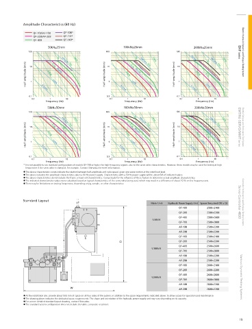
Amplitude Characteristics (60 Hz)

                 QF-10B/AF-10B  QF-70B*
                 QF-20B/AF-20B  QF-110*
                 QF-40B         QF-140*
                        50kN±25mm                            100kN±25mm                        200kN±25mm
               100           1G  100cm/s 10G  100G  100           1G  100cm/s 10G  100G  100  10cm/s  1G  100cm/s 10G  100G  EHF Series  Electric Hydraulic Dynamic and Fatigue Testing System


             Half-amplitude (mm)  10 1  0.01G  0.1G  10cm/s  Half-amplitude (mm)  10 1  0.01G  0.1G  10cm/s  Half-amplitude (mm)  10 1  0.01G  0.1G


                          1cm/s
                                                                 1cm/s

               0.1   0.1cm/s                         0.1   0.1cm/s                     0.1   0.1cm/s  1cm/s
                0.1      1       10                   0.1      1      10                0.1      1       10
                       Frequency (Hz)                        Frequency (Hz)                     Frequency (Hz)
                        50kN±50mm                            100kN±50mm                        200kN±50mm
               100             100cm/s 10G  100G    100           1G  100cm/s 10G  100G  100         1G  100cm/s 10G  100G


             Half-amplitude (mm)  10 1  0.01G  0.1G  10cm/s  1G  Half-amplitude (mm)  10 1  0.01G  0.1G  10cm/s  Half-amplitude (mm)  10 1  0.01G  1cm/s  10cm/s  EMT/NJ-SERVO/MMT Series  Electric Fatigue and Endurance Test System


                                                                                                     0.1G
                           1cm/s
                                                                1cm/s

               0.1   0.1cm/s                         0.1   0.1cm/s                     0.1   0.1cm/s
                0.1      1       10                   0.1      1      10                0.1      1      10
                       Frequency (Hz)                        Frequency (Hz)                     Frequency (Hz)
            * It is not possible to use standard con gurations of models QF-70B or higher for high-frequency regions, due to the servo valve characteristics. However, these models may be used for testing at high
             frequencies if the servo valve is changed, for example. Contact Shimadzu for more information.
             The above characteristic curves indicate the relation between half-amplitude and cycle speed, given sine wave motion at the rated load level.
             The above indicates the amplitude characteristics given a 60 Hz power supply. Characteristics with a 50 Hz power supply will be about 5/6 of indicated values.
             The above characteristics do not include the frame or load cell characteristics. Compensate for the in uence of these factors to determine actual amplitude characteristics.
             The indicated characteristics values were calculated based on typical characteristics of the servo valve being used, which may result in a difference of about 10 % on the frequency axis.
             There may be limitations on testing frequencies, depending on jig, sample, or other characteristics.


            Standard Layout
                                                                          Main Unit  Hydraulic Power Supply Unit Space Required (W x D)  Servo Controller 4830  Controller for Dynamic and Fatigue Testing Systems
                                                                                       QF-10B        2500×2100
                                                                                       QF-20B        2500×2200
                                                                                       QF-40B        2500×2600
                                                                           U50kN
                                                                                       QF-70B        2500×2800
                                                                                        AF-10B       2500×2200
                                                                                        AF-20B       2500×2200
                                                                                       QF-10B        2500×2100
                                                                                       QF-20B        2500×2200
                                                                                       QF-40B        2500×2600
                                                                          U100kN
                                                                                       QF-70B        2500×2800
                                                                                        AF-10B       2500×2200
                                                                                        AF-20B       2500×2200
                                                                                       QF-10B        2600×2100
                                                                                       QF-20B        2600×2200
                                                                                       QF-40B        2600×2600
                                                                          U200kN                                     Various Dynamic Testing Systems
                                                                                       QF-70B        2600×2800
                                                                                        AF-10B       2600×2200
                                                                                        AF-20B       2600×2200
             At the installation site, provide about 500 mm of space on all four sides of the system, in addition to the space requirements indicated above, to allow access for operation and maintenance.
             The drawing above indicates the dedicated space requirements. The shape and orientation of the hydraulic power supply unit may vary depending on its capacity.
             For a more detailed standard layout drawing, contact Shimadzu.
             The standard system con guration does not include the table, computer, or printer.


                                                                                                                      19
   14   15   16   17   18   19   20   21   22   23   24