
Page 49 - Shimadzu Dynamic and Fatigue Testing Systems
P. 49
Specifications
Model MMT-11NV-2 MMT-101NV-10 MMT-250NV-10 MMT-500NV-10
Test force ±10N ±100N ±250N ±500N
Piston stroke ±2mm ±10mm
Cycle speed 60Hz 100Hz
Controlled items Test force and stroke (two can be added as options)
Within ±1 % of indicated value or Within ±0.5 % of indicated value or ±0.02 % of EHF Series Electric Hydraulic Dynamic and Fatigue Testing System
Test force ±0.02 % of maximum dynamic
Indication accuracy test force, whichever is greater maximum dynamic test force, whichever is greater
Stroke Stroke: Within +1 % of indicated value or ±0.1 % of maximum stroke, whichever is greater
Installation space (W × D × H) Approx. 1000 × 500 × 1200 mm
Actuator mount Bottom Either top or bottom mount
Total weight Approx. 80 kg Approx. 100 kg Approx. 120 kg Approx. 150 kg
Power requirements 1Ø 100V 500VA 1Ø 100V 1kVA
Minimal temperature variations (+10 to +40 °C recommended, with temperature variations within ±5 °C)
Site requirements Low humidity Not exposed to direct air flow from heating or cooling systems
No direct sunlight Low dust No significant vibration
Servo Controller 4830 Servo Controller 4830 EMT/NJ-SERVO/MMT Series Electric Fatigue and Endurance Test System
Main unit Power ampli er Power ampli er
Units: mm
10 to 250 N 500N
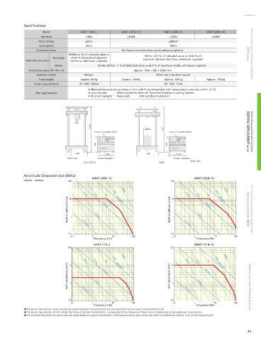
Amplitude Characteristics (60Hz)
No load 100 0.01G MMT-500N-10 10G 100G 100 0.01G MMT-250N-10 10G 100G
1G
1G
Half-amplitude (mm) 10 1 0.1G 10cm/s 100cm/s Half-amplitude (mm) 10 1 0.1G 10cm/s 100cm/s Servo Controller 4830 Controller for Dynamic and Fatigue Testing Systems
1cm/s
1cm/s
0.1 0.1cm/s 0.1 0.1cm/s
0.1 1 10 100 0.1 1 10 100
Frequency (Hz) Frequency (Hz)
MMT-11N-2 MMT-101N-10
100 0.01G 1G 10G 100G 100 0.01G 1G 10G 100G
Half-amplitude (mm) 10 1 0.1G 10cm/s 100cm/s Half-amplitude (mm) 10 1 0.1G 10cm/s 100cm/s Various Dynamic Testing Systems
1cm/s
1cm/s
0.1 0.1cm/s 0.1 0.1cm/s
0.1 1 10 100 0.1 1 10 100
Frequency (Hz) Frequency (Hz)
The above characteristic curves indicate the relation between half-amplitude and cycle speed during sine wave motion (without load).
The above characteristics do not include the frame or load cell characteristics. Compensate for the in uence of these factors to determine actual amplitude characteristics.
The indicated characteristics values were calculated based on typical characteristics of the actuator being used, which may result in a difference of about 10 % on the frequency axis.
49