
Page 47 - Shimadzu Dynamic and Fatigue Testing Systems
P. 47
Specifications
Model NJ-1kNV-100 NJ-5kNV-100 NJ-10kNV-100 NJ-20kNV-100 NJ-30kNV-100
Dynamic ±1 kN ±5 kN ±10 kN ±20 kN ±30 kN
Test Force
Static ±1 kN ±5 kN ±10 kN ±20 kN ±30 kN
±100 mm
Stroke (Full stroke) (200 mm)
Single wave: 20 cm/sec (loaded); Single wave: 72 cm/sec (loaded); Single wave: 40 cm/sec (loaded);
Max. Speed
Continuous: 15 cm/sec (loaded, sine wave) Continuous: 50 cm/sec (loaded, sine wave) Continuous: 30 cm/sec (loaded, sine wave) EHF Series Electric Hydraulic Dynamic and Fatigue Testing System
Sensor Indicator Test Force ±0.5% indicated value, or ±0.02% of the load cell rating, whichever is larger
Accuracy Stroke ±1% indicated value, or ±0.1% of the rating, whichever is larger
L0 980 mm 1080 mm 1260 mm 1385 mm 1550 mm
Actuator 680 mm 730 mm 750 mm 840 mm 820 mm
Unit Size L1
L2 130 mm 140 mm 140 mm
Servo W×H×D 700×715×552 mm 700×1250×350 mm
Ampli er Size
Weight Approx. 30 kg Approx. 70 kg Approx. 110 kg Approx. 180 kg Approx. 220 kg
3-phase 200 V, 7 kVA 3-phase 200 V, 12 kVA 3-phase 200 V, 18 kVA 3-phase 200 V, 23 kVA
Power Requirements
Single-phase 100V 1.5kVA Single-phase 100V 1.5kVA Single-phase 100V 1.5kVA Single-phase 100V 1.5kVA
Compatible Controllers Servo Controller 4830
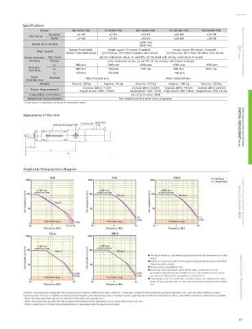
Amplitude Characteristics See amplitude characteristics diagrams.
Each system is adaptable for longer stroke/higher speed.
Appearance of the Unit
Servo motor
Trunnion shaft
Displacement gauge (DTF) EMT/NJ-SERVO/MMT Series Electric Fatigue and Endurance Test System
L2
L1
L0
Amplitude Characteristics Diagram
1kN 5kN 10kN No load
1000 1000 1000
Rated load
±100 mm
±100 mm
±100 mm 100 speci cations 50cm/s 100 speci cations 50cm/s
Half-Amplitude (mm) 10 15cm/s Half-Amplitude (mm) 10 Half-Amplitude (mm) 10 Servo Controller 4830 Controller for Dynamic and Fatigue Testing Systems
speci cations
100
1G (
Prohibited range 0.5G Prohibited range 0.8G Prohibited range (
1 1 1
0.1 1 0.3 G 10 0.1 1 10 0.1 1 10
Frequency (Hz) Frequency (Hz) Frequency (Hz)
20kN 30kN
1000 1000
±100 mm
±100 mm 30cm/s 100 speci cations 30cm/s
Half-Amplitude (mm) Half-Amplitude (mm) The gure above is a calculated value obtained from the characteristics of the
speci cations
100
motor.
If there is a resonance point in the system including the test piece, avoid that
frequency when using it.
10
10
The jig mass is calculated as 5 kg.
At the top of the amplitude characteristic value, it stops due to heat
0.8G 0.8G generation depending on the number of tests. The number of tests can be
Prohibited range 0.6G Prohibited range 0.6G increased by changing the test speed or cooling the air. Various Dynamic Testing Systems
1 1 Depending on the test conditions, resonance may occur including the tester
0.1 1 10 0.1 1 10 body, test jig, and specimen. In that case, remove the resonance point before
Frequency (Hz) Frequency (Hz) use.
Similarly, in the frequency sweep test, the resonance point may be included in the test conditions. In that case, change the test conditions and jig con guration, etc., and use under conditions where
resonance does not occur. In addition to the resonance frequency, the inertial force due to vibration may be superimposed on the load cell detection value. (Case where resonance is likely to be a problem)
· When the upper and lower jigs are not restrained. (Ball seat pressure plate, etc.)
· When the mass of the jig under the cell is large and the distance to the load point is long. (Tests with in-tank rods, etc.)
· When a lateral force / moment (lateral displacement) is generated when the specimen is loaded.
47