
Page 43 - Shimadzu Dynamic and Fatigue Testing Systems
P. 43
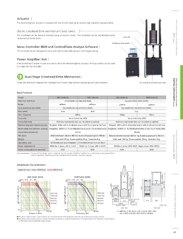
Actuator
            The electromagnetic actuator is coupled with low-friction bearings to achieve high waveform reproducibility.

            Electric Crosshead Drive and Manual Clamp Levers
            The crosshead can be raised or lowered using an electric switch. The crosshead can be immobilized easily
                                                                                   Load cell
            using manual clamp levers.                                                                              EHF Series  Electric Hydraulic Dynamic and Fatigue Testing System
                                                                            Emergency stop switch
            Servo Controller 4830 and Control/Data Analysis Software
            The controller allows high-performance and high-functionality dynamic and fatigue testing.

            Power Amplifier Unit
            Internal electronic power circuits are used to drive the electromagnetic actuator. The top surface can be used
            as a table for the controller.


                  Dual-Stage Crosshead Drive Mechanism

            Using two buttons to operate the crosshead and clamps helps prevent operating errors and accidents.  Air-cooling unit (inside main unit)


            Specifications                                                                                          EMT/NJ-SERVO/MMT Series  Electric Fatigue and Endurance Test System
             Model                     EMT-1kNV-30         EMT-1kNV-50         EMT-5kNV-30        EMT-5kNV-50
             Maximum test force             ±1 kN (static and dynamic tests)        Dynamic±5kN, Static±3.5kN
             Stroke                      ±30mm               ±50mm              ±30mm               ±50mm
             Cycle speed and amplitude     See amplitude characteristics charts.  See amplitude characteristics charts.
             Max. speed                   1m/s               2m/s                          1m/s
             Max. frequency                        200Hz                         100Hz              100Hz
             Controller                        Servo Controller 4830                  Servo Controller 4830
             Controlled items          Test force and stroke (two can be added as option)  Test force and stroke (two can be added as option)
             Test force range and indication accuracy  Rangeless   Within ±0.5 % of indicated value or ±0.02 % of maximum test force  Rangeless   Within ±0.5 % of indicated value or ±0.02 % of maximum test force
             Stroke range and indication accuracy Rangeless   Within ±1 % of indicated value or ±0.1 % of rated value  Rangeless   Within ±1 % of indicated value or ±0.1 % of rated value
             Frame drive mechanism                 Electric                               Electric
             Test space            Distance between columns: 460 mm  Jig mounting spacing: 0 to 700 mm  Distance between columns: 460 mm  Jig mounting spacing: 0 to 700 mm
             Weight                   Main unit: 510 kg   Power amplifier: 60 kg   Controller: 8 kg  Main unit: 1100 kg   Power amplifier: 300 kg   Controller: 8 kg
             Operating noise       62 dB (reference value measured 1 m from front of main unit and floor)  -
             Power requirements   50/60 Hz, 3-phase, 200 V, 4 kVA  50/60 Hz, 3-phase, 200 V, 5 kVA  50/60Hz 3-phase 200V 9kVA, Single-phase 100V 300VA  Servo Controller 4830  Controller for Dynamic and Fatigue Testing Systems
             Power consumption at max load  4kW              5kW                 5kW                 6kW
            Site requirements : No special foundation work is required, but the system should be installed on a suf ciently strong ground  oor,
                      with no basement. Machines must be installed with anchor bolts to prevent tipping.


            Amplitude Characteristics
                 No load  500 N load  1000 N load

                   EMT-1kNV-30/50                  EMT-5kNV-30/50                                            0~900
              0.01G  0.1G  1G  10G           0.01G  0.1G  1G  10G
             100                            100                                                         620
                                                                                   460  410 to 1120  max. 2700  183
                                                                           (165)  Controller  Approx. 2170  1535  1145  max. 2142
             Half-amplitude (mm)  1  200cm/sec  Half-amplitude (mm)  1  200cm/sec  (700)  ampli er  Main unit  Approx. 710  65  Anchor bolt
                                             10
              10
                                   100cm/sec
                                                                  100cm/sec
                                                                             Power
                                                                  50cm/sec
                                   50cm/sec
                                                                  20cm/sec
                                   20cm/sec
                                                                                   725
                                                                             (524)
                                                                                        M12 in 4
             0.1
                                             0.1
                                                                                (1360)
                                   10cm/sec
                                                                  10cm/sec
                                                                                        locations
                                                                              (Depth: 650)  depth  570  800  Units: mm  Various Dynamic Testing Systems
                                                                                  EMT-1kN              EMT-5kN
             0.01                           0.01
               0.1   1    10    100 200       0.1   1    10    100 200         In addition to the above unit, a blower (5kN, 1kN)
                    Frequency (Hz)                  Frequency (Hz)               and a 4830 controller (5kN) will be installed.
             The above characteristic curves indicate the relation between half-amplitude and cycle speed during sine wave motion.
             The above characteristics do not include the frame, load cell, or sample characteristics. Compensate for the in uence of these factors
             to determine actual amplitude characteristics.
                                                                                                                     43