
Page 65 - Shimadzu Dynamic and Fatigue Testing Systems
P. 65
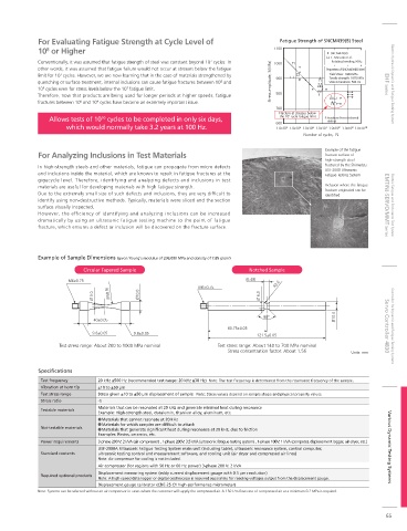
For Evaluating Fatigue Strength at Cycle Level of                        Fatigue Strength of SNCM439(B) Steel
            10  or Higher                                                          1100             SNCM439(B)
               8
                                                                                                    C. Masuda et al.
                                                                7
            Conventionally, it was assumed that fatigue strength of steel was constant beyond 10  cycles. In   1000   Rotating bending,50Hz
            other words, it was assumed that fatigue failure would not occur at stresses below the fatigue   Properties of SNCM439(B) Steel
                   7
            limit for 10  cycles. However, we are now learning that in the case of materials strengthened by   900  f  Yield stress: 1444 MPa
                                                                                                    Tensile strength: 1870 MPa
            quenching or surface treatment, internal inclusions can cause fatigue fractures between 10  and   Stress amplitude, S(MPa)  f f  Vickers hardness: 592 Hv  EHF Series  Electric Hydraulic Dynamic and Fatigue Testing System
                                                                   8
              9
                                       7
            10  cycles even for stress levels below the 10  fatigue limit.                       f
            Therefore, now that products are being used for longer periods at higher speeds, fatigue   800  f  f
            fractures between 10  and 10  cycles have become an extremely important issue.          f
                         8
                              9
                                                                                    700
                                                                                     Fracture at stresses below
                Allows tests of 10  cycles to be completed in only six days,         the 10 7  cycle fatigue limit  f: Fracture from internal
                               10
                                                                                                   defect
                     which would normally take 3.2 years at 100 Hz.                 600
                                                                                    1.0x10 4 1.0x10 5 1.0x10 6 1.0x10 7 1.0x10 8 1.0x10 9 1.0x10 10
                                                                                            Number of cycles,  N
                                                                                                  Example of the fatigue
            For Analyzing Inclusions in Test Materials                                            fracture surface of
                                                                                                  high-strength steel
            In high-strength steels and other materials, fatigue can propagate from micro defects   fractured by the Shimadzu
                                                                                                  USF-2000 Ultrasonic
            and inclusions inside the material, which are known to result in fatigue fractures at the   Fatigue Testing System
            gigacycle level. Therefore, identifying and analyzing defects and inclusions in test
            materials are useful for developing materials with high fatigue strength.             Inclusion where the fatigue
                                                                                                  fracture originated can be
            Due to the extremely small size of such defects and inclusions, they are very dif cult to   identi ed
            identify using non-destructive methods. Typically, materials were sliced and the section
            surface visually inspected.                                                                             EMT/NJ-SERVO/MMT Series  Electric Fatigue and Endurance Test System
            However, the ef ciency of identifying and analyzing inclusions can be increased
            dramatically by using an ultrasonic fatigue testing machine to the point of fatigue
            fracture, which ensures a defect or inclusion will be discovered on the fracture surface.
            Example of Sample Dimensions (given Young's modulus of 206,000 MPa and density of 7.85 g/cm 3 )
                          Circular Tapered Sample                           Notched Sample
                     M6×0.75                                               (6.49)
                                                            M6×0.75                R3.0
                             Ø 3.0  (R58.9)  Ø10.0                             Ø 6.0


                                                                                90°                  Ø10.0
                             40±0.05
                                                                     60.75±0.05                                     Servo Controller 4830  Controller for Dynamic and Fatigue Testing Systems
                             9.8±0.05    9.8±0.05
                                                                              121.5±0.05
                   Test stress range: About 200 to 1000 MPa nominal  Test stress range: About 140 to 700 MPa nominal
                                                                     Stress concentration factor: About 1.56  Units: mm


            Specifications
             Test frequency   20 kHz ±500 Hz (recommended test range: 20 kHz ±30 Hz)  Note: The test frequency is determined from the resonance frequency of the sample.
             Vibration at horn tip  ±10 to ±50  m
             Test stress range  Stress given ±10 to ±50  m displacement of sample   Note: Stress values depend on sample shape and physical property values.
             Stress ratio     -1
                              Materials that can be resonated at 20 kHz and generate minimal heat during resonance
             Testable materials
                              Example: High-strength steel, duralumin, titanium alloy, aluminum, etc.
                               Materials that cannot resonate at 20 kHz
                               Materials for which samples are difficult to attach
             Not-testable materials  Materials that generate significant heat during resonance at 20 kHz, due to friction
                              Examples: Resins, ceramics, etc.
             Power requirements  3-phase 200 V: 2 kVA (air compressor) , 1-phase 200V: 3.5 kVA (ultrasonic fatigue testing system) , 1-phase 100V: 1 kVA (computer, displacement logger, air dryer, etc.)
                              USF-2000A Ultrasonic Fatigue Testing System main unit (including table), ultrasonic resonance system, control computer,   Various Dynamic Testing Systems
             Standard contents  ultrasonic testing control and measurement software, and cooling unit (air dryer and compressed air lines)
                              Note: Air compressor for cooling is not included.
                              Air compressor (for regions with 50 Hz or 60 Hz power) 3-phase 200 V: 2 kVA
                              Displacement measuring system (eddy current displacement gauge with 0.5  m resolution)
             Required optional products
                              Note: A high-speed data logger or digital oscilloscope is required separately for reading voltages output from the displacement gauge.
                              Displacement gauge calibrator (CDE-25 C1 high-performance micrometer)
            Note: Systems can be selected without an air compressor in cases where the customer will supply the compressed air. A 150 L/m  ow rate of compressed air at a minimum 0.2 MPa is required.


                                                                                                                     65