
Page 19 - Shimadzu SPM-9700HT
P. 19
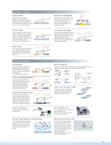
Standard Functions
               Contact Mode                                  Lateral Force Mode (LFM)
               This mode creates an image of                 By detecting the amount of twist in the
               displacement in the sample height             cantilever during contact mode scanning,
               direction by scanning the sample surface      an image can be created from
               with the repulsive force acting between       information corresponding to lateral
               the cantilever tip and sample kept constant.   forces (friction) acting between the
               Force curves can be measured as well.         sample and cantilever.

               Dynamic Mode                                  Force Modulation Mode
               This mode vibrates the cantilever near its    This mode vibrates the sample at constant
               resonant frequency. Since the amplitude       amplitude and frequency during contact
               changes as the cantilever approaches the      mode scanning. The cantilever response is
               sample, a sample height displacement          detected by separating it into its
               image can be created by moving the probe      amplitude and phase components. This
               to keep the amplitude constant.               allows creating an image of differences in
               Force curves can be measured as well.         sample surface properties.

               Phase Mode
               This mode detects the phase shift delay in
               the cantilever vibration during dynamic
               mode scanning. This allows creating an
               image of differences in sample surface
               properties.


                Optional Functions

               Current Mode                                  Nano 3D Mapping
               This mode applies a voltage between a         A force curve can be measured for each point in observed image data to observe a
               conductive cantilever and sample              distribution of sample mechanical properties or adhesive strength.
               during contact mode scanning and         A
               creates an image from the distribution           Adhesion
               of current  ows.                                   layer
               I/V measurement is also possible.
                                                                 Sample
               Surface Potential Mode (KFM)
               An image can be created from the
               electric potential of the sample surface
               by applying an alternating current
               electrical signal to a conductive   +  +
               cantilever and detecting the static   +  +  V
               electric force acting between the             Vector Scanning (special order)
               sample surface and cantilever.   + + + +  + +  The scanning direction, force between
                                        +
                                       +
                                                             the probe and sample, or the applied
               Magnetic Force Mode (MFM)                     voltage can be programmed to allow
                                                             scanning according to a program.
               This mode scans the sample with a
               magnetic tipped cantilever kept at a
               constant distance from the sample. An
               image can be created from magnetic
               information of the sample surface
               obtained by detecting the magnetic
               force from the magnetic leakage  eld.   N  S  N  S
               Sample Heating Unit                           Light Irradiation Unit
               The sample can be loaded into the             This unit enables the use of a  ber optic
               unit and heated.                              light to irradiate sample
                                                             surfaces. It does not include the light
                                                             source or the optical  ber.

               Petri Dish Type Solution Cell (special order)  Electrochemical Solution Cell
               The sample is attached to the bottom of       This cell is used for AFM observations
               a small petri dish, which is then  lled       of sample surface changes while an
               with solution. By scanning with the           electrochemical reaction occurs in an
               cantilever immersed in solution, AFM          electrolytic solution. The cell includes
               observations can be performed in              three standard electrodes (working,
               solutions.                                    counter, and reference) and includes
                                                             a petri dish type solution cell.
                                                             (Does not include the
                                                             separately-ordered electrochemical
                                                             controller (potentiostat).)


                                                                                                                  19