Page 18 - Shimadzu EPMA-8050G
P. 18

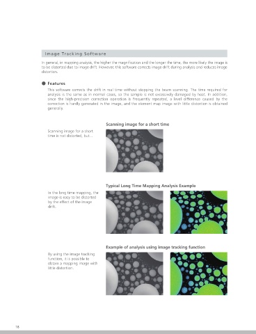
Image Tracking Software                                                                                            Transmitted Polarization Observation System

                     In general, in mapping analysis, the higher the magni cation and the longer the time, the more likely the image is   With this option, some of the functions of a transmission polarization
                     to be distorted due to image drift. However, this software corrects image drift during analysis and reduces image   microscope, widely used in mineralogy and crystallography research, are
                     distortion.                                                                                                        achieved with an EPMA optical observation system. Rock  akes and other  aked
                                                                                                                                        samples are exposed to polarized light from below, and the transmitted light is
                                                                                                                                        observed with an EPMA optical observation system, enabling polarization
                     ˔ Features
                                                                                                                                        observation.
                        This software corrects the drift in real time without stopping the beam scanning. The time required for         When samples are observed with a transmission polarization microscope already
                        analysis is the same as in normal cases, so the sample is not excessively damaged by heat. In addition,         in the customer's possession, and are then observed or analyzed via EPMA
                        since the high-precision correction operation is frequently repeated, a level difference caused by the          based on the knowledge obtained, the observational functions of this product
                        correction is hardly generated in the image, and the element map image with little distortion is obtained       will be useful in searching for target positions. Observation and analysis can be
                        generally.                                                                                                      performed using an electron beam while performing polarization observations.
                                                                                                                                        ˔  Features
                                                   Scanning image for a short time                                                      Observations can be performed in both open nicol and crossed nicols modes.
                        Scanning image for a short                                                                                                        Sample Observation in                         Sample Observation in
                        time is not distorted, but...                                                                                                     Open Nicol Mode                               Crossed Nicols Mode
                                                                                                                                                          In open nicol mode, light passed through a    In crossed nicols mode, observation is
                                                                                                                                                          polarizing element (polarizer) is used to     performed through a polarizing element
                                                                                                                                                          illuminate the sample from below. The         (analyzer) configured to an angle
                                                                                                                                                          transmitted light is then observed with the EPMA   orthogonal to the polarizer. Mineral types
                                                                                                                                                          optical microscope. Mineral types are inferred by   are inferred from interference colors that
                                                                                                                                                          observing the boundary between neighboring    appear depending on the type and thickness
                                                                                                                                                          minerals, and comparing refractive indices and   of the mineral sample.
                                                                                                                                                          studying the presence or absence of coloration.
                                                                                                                                        Polarization observations can be performed    Sample Observations When the Polarization Angle Is Changed
                                                                                                                                        without rotating the sample.
                                                   Typical Long Time Mapping Analysis Example                                           With this system, the angle of the polarized light is changed by
                                                                                                                                        controlling the rotation angle of the polarizer and analyzer. As a result,
                        In the long time mapping, the                                                                                   observations can be performed without rotating the sample.
                        image is easy to be distorted
                        by the effect of the image
                        drift.                                                                                                                                                          Polarization Angle: 85°  Polarization Angle: 113°
                                                                                                                                        Collisions between the light guide and sample base due to improper operation are prevented.
                                                                                                                                        When polarization observations are performed, the polarization observation sample base is used, and the tip of the polarization illumination optical path
                                                                                                                                        (light guide) is moved directly below the sample. When a standard sample base is used, the light guide tip is retracted to prevent collisions with the sample
                                                                                                                                        base. This system identifies the polarization observation sample base, and controls the stage and light guide accordingly, enabling it to prevent collisions due
                                                                                                                                        to improper operations.
                                                                                                                                        The control window for polarization observations is linked   The stage map for the polarization
                                                                                                                                        to insertion of the polarization observation sample base.  observation sample base can be used.
                                                   Example of analysis using image tracking function
                        By using the image tracking
                        function, it is possible to
                        obtain a mapping image with
                        little distortion.
                                                                                                                                                                       Window display is linked to
                                                                                                                                                                       the polarization observation
                                                                                                                                                                       sample base


                                                                                                                                               Operational Windows in the Observation Window        Stage Map Selection Window
                                                                                                                                        The control window for polarization observations displayed on the PC is linked to insertion   The stage can be moved to the intended observation
                                                                                                                                        of the polarization observation sample base into the instrument. Operations following   position utilizing the stage map corresponding to the
                                                                                                                                        insertion of the polarization observation sample base can be smoothly performed.  polarization observation sample base.
                                                                                                                                                                                                                        EPMA-8050G
                                                                                                                                                                                                                         Electron Probe Microanalyzer
        18                                                                                                                                                                                                                                  19
   13   14   15   16   17   18   19   20   21   22   23