Page 3 - Shimadzu Microservo MMT Series
P. 3

Features


             Compact and lightweight body                       An electrical power source is the only utility
                                                                required
                                                                required
             Installation is easy due to lightweight and small body
                                                                Other utilities such as water and air are unnecessary
             Quiet operation allows installation at any place   Easy operation
             Operation noise has been reduced compared to hydraulic systems


            Working Principle (Control of Micro Loads)

            The load generator is comprised of a permanent magnet and a force                  F
            coil as shown in the diagram on the right. The permanent magnet is
            fixed and the coil moves up and down.
            When a current is passed through the coil, an electromagnetic force F
            proportional to this coil current is generated according to the
            following equation:
                                                                                   N        S        N
                   F = 2πrnBI
                          r  : coil radius
                          n  : turns of coil
                          B
                           I  : coil current
            The micro load is controlled with great precision by generating the
            electromagnetic force through the control of the coil current using the
            closed loop system.


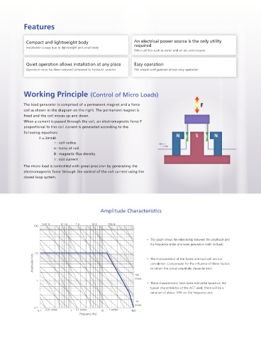
                                                Amplitude Characteristics


                     0.01 G  0.1 G  1 G     10 G    100 G
                 100

                                                                      • This graph shows the relationship between the amplitude and
                                                                       the frequency under sine wave generation (with no load).

                Amplitude (mm)  10                                    • The characteristics of the frame and load cell are not

                                                                       considered. Compensate for the influence of these factors
                                                                       to obtain the actual amplitude characteristics.
                                                                100
                                                                cm/sec
                  1
                                                                      • These characteristics have been estimated based on the
                                                                       typical characteristics of the ACT used; there will be a
                                                                       variation of about 10% on the frequency axis.

                                                                10
                                                                cm/sec
                 0.1
                      0.01 cm/sec    0.1 cm/sec     1 cm/sec
                   0.1            1             10            100
                                      Frequency (Hz)
   1   2   3   4   5   6   7   8