
Page 25 - Shimadzu AGX-V2 Series
P. 25
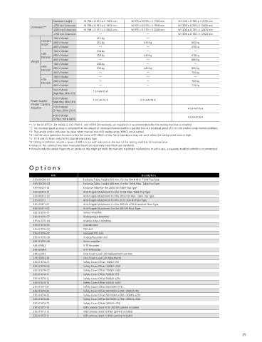
Standard Height  W 798 × D 515 × H 1582 mm  W 975 × D 579 × H 1708 mm  W 1206 × D 765 × H 2170 mm
                          +250 mm Extension  W 798 × D 515 × H 1832 mm  W 975 × D 579 × H 1958 mm  W 1206 × D 765 × H 2420 mm
               Dimensions* 6
                          +500 mm Extension  W 798 × D 515 × H 2082 mm  W 975 × D 579 × H 2208 mm  W 1206 × D 765 × H 2670 mm
                          +750 mm Extension    —                     —              W 1206 × D 765 × H 2920 mm
                          100 V Model         210 kg                 —                     —
                    Standard  200 V Model     210 kg                410 kg                660 kg
                    Height
                          400 V Model          —                     —                    670 kg
                          100 V Model         230 kg                 —                     —
                    +250   200 V Model        220 kg                420 kg                670 kg
                    Extension
               Weight     400 V Model          —                     —                    680 kg
                          100 V Model         240 kg                 —                     —
                    +500   200 V Model        230 kg                440 kg                690 kg
 AGX-10kNV2D  AGX-50kNV2D  AGX-50kNV2  Extension  400 V Model  —     —                    700 kg
                          100 V Model          —                     —                     —
 System Specifications  +750   200 V Model      —                     —                    700 kg
                    Extension
                          400 V Model          —                     —                    710 kg
 Model Name  AGX-10kNV2D  AGX-20/50kNV2D  AGX-20/50kNV2  100 V Model  1.5 kVA/15 A  —      —
 Max. Loading Capacity  10 kN  50 kN  (Single-Phase, 100 to 115 V)
 Loading Method  AC servomotor drive  200 V Model
               Power Supply/                2.0 kVA/10 A          5.5 kVA/30 A             —
 Within ±0.5 % error of the indicated test force (in a range from 1/1000 to 1/100 of the load cell rated capacity)   (Single-Phase, 200 to 230 V)
 High-Accuracy Type  Within ±0.3 % error of the indicated test force (in a range from 1/100 to 1/1 of the load cell rated capacity)  Breaker Capacity   200 V Model
 Compatible with JIS B7721 Class 0.5, EN 10002-2 Grade 0.5, ISO 7500-1 Class 0.5, BS 1610 Class 0.5, DIN 51221 Class 0.5, and ASTM E4  Required  —  —  4.5 kVA/15 A
                          (3-Phase, 200 to 230 V)
 Test Force   Within ±1 % error of the indicated test force (in a range from 1/2000 to 1/1000 of the load cell rated capacity)  400 V Model
 Measuring   Within ±0.5 % error of the indicated test force (in a range from 1/1000 to 1/100 of the load cell rated capacity)   (3-Phase, 380 to 400 V)  —  —  4.0 kVA/10 A
 Range* 1  Wide Ranging Type  Within ±0.3 % error of the indicated test force (in a range from 1/100 to 1/1 of the load cell rated capacity)
 Compatible with JIS B7721 Class 1, EN 10002-2 Grade 1, ISO 7500-1 Class 1, BS 1610 Class 1, DIN 51221 Class 1, and ASTM E4  *1: In the JIS B7721, EN 10002-2, ISO 7500-1, and ASTM E4 standards, an inspection is recommended after the testing machine is installed.
               *2: The crosshead speed accuracy is calculated from the amount of crosshead movement within a specified time at a crosshead speed of 0.5 to 500 mm/min under normal conditions.
 Within ±1 % error of the indicated test force (in a range from 1/1000 to 1/1 of the load cell rated capacity)
 Compatible with JIS B7721 Class 1, EN 10002-2 Grade 1, ISO 7500-1 Class 1, BS 1610 Class 1, DIN 51221 Class 1, and ASTM E4  *3: The tensile stroke indicates the value when manual non-shift wedge grips (MWG) are attached.
 Standard-Accuracy Type  *4: Use the voice operation function when the noise is 55 dB(A) or less. Voice operations may not work when the background noise is high.
 Within ±1 % error of the indicated test force (in a range from 1/500 to 1/1 of the load cell rated capacity)  *5: 10 N and 20 N are only for the standard-accuracy type.
 Compatible with JIS B7721 Class 1, EN 10002-2 Grade 1, ISO 7500-1 Class 1, BS 1610 Class 1, DIN 51221 Class 1, and ASTM E4  *6: During installation, ensure a space of 600 mm on each side and at the rear of the testing machine for maintenance.
               • Values in this catalog have been measured based on separately prescribed test standards.
 Crosshead Speed Range* 2  0.0005~3000 mm/min  0.0005~1500 mm/min  0.00005~1500 mm/min  • If small conductive sample fragments are produced, they might get inside the main unit, resulting in malfunctions. In such a case, a separately installed controller is recommended.
 Maximum Crosshead Return Speed  3000 mm/min  2000 mm/min
 Crosshead Speed Accuracy  ±0.1 %
 Crosshead Speed and Permitted Test Force  Up to the maximum load capacity for all speed ranges
 Crosshead   Measurement System  Battery-less multi-turn absolute encoder
 Position Detection  Positional Accuracy  Within ±0.05 % of the indicated value, but ±0.01 mm when the indicated value is below 20 mm  Options
 Crosshead Position Control Resolution  12.5 nm  8.33 nm
                         P/N                                       Description
 180 to 1150  200 to 1150  215 to 1265
 Standard Height  339-90000-01          Exclusive Table, Height 650 mm, for the 10 kN Max. Table-Top Type
 (0 to 550)  (20 kN:0 to 750 mm, 50 kN:0 to 690 mm)  (20 kN:0 to 860 mm, 50 kN:0 to 800 mm)
                339-90000-02            Exclusive Table, Height 400 mm, for the 10 kN Max. Table-Top Type
 180 to 1375  200 to 1375  215 to 1490
 Crosshead-Table  +250 mm Extension  (0 to 775 mm)  (20 kN:0 to 975 mm, 50 kN:0 to 915 mm)  (20 kN:0 to 1085 mm, 50 kN:0 to 1025 mm)  339-90001-01  Exclusive Table for the 20/50 kN Table-Top Type
 Clearance (mm)  336-00313-01           Anti-Topple Attachment for the 10 kN Max. Table-Top Type
 (Tensile Stroke)* 3  +500 mm Extension  180 to 1600  200 to 1600  215 to 1715  336-00313-02  Anti-Topple Attachment for the 20/50 kN Max. Table-Top Type
 (0 to 1000 mm)  (20 kN:0 to 1200 mm, 50 kN:0 to 1140 mm)  (20 kN:0 to 1310 mm, 50 kN:0 to 1250 mm)
                336-00311               Anti-Topple Attachment for the 20 to 300 kN Floor Type
 215 to 1940
 +750 mm Extension  —  —  336-00311-01  Anti-Topple Attachment for the 300 kN +750 Extension Floor Type
 (20 kN:0 to 1535 mm, 50 kN:0 to 1475 mm)
                336-00311-02            Anti-Topple Attachment for the 600 kN Floor Type
 Effective Test Width  420 mm  500 mm  600 mm
                336-01076-01            Sensor Amplifier
 Data Capture Rate  10 kHz max.  336-01076-07  Analog Input Amplifier
 Direction of Tension  60 kN/mm  180 kN/mm
 Frame Rigidity  336-01076-04           Analog Output Amplifier
 Direction of Compression  60 kN/mm  180 kN/mm  336-01076-05  Counter Unit
 • Test force/stress value display  • Touch load detection  • Test piece protection  336-01076-03  PIO Unit
 • Stroke display  • Switching display languages to   • Timer  336-01076-02  Insulated PIO Unit
 • Test force auto zero  Japanese/English/Chinese language  • Calculator  336-01076-08  Analog Recorder Unit
 • Test force auto calibration  • Switching display unit  • Light  336-01076-06  Strain amplifier
 • Automatic loading of load cell characteristic values  • Standby Power Savings  • Sound (Choose between standard and clear)  345-05842  X-TP Recorder
 • Fine adjustment of crosshead position (Button/Dial)  • Self-check  • Audio Output (Japanese/English/Chinese)  345-05843  X-TYP Recorder
 Standard Functions  • Interlock function (Safety cover)  • Auto return  • 6 internal unit ports
 When the displacement gauge is connected  • Setting Jig distance   (One of the ports is dedicated to testing power.)  346-55042  One-Touch Load Cell Replacement Function
 • Displacement/strain value display function  • Voice operation function *4  346-55042-01  One-Touch Load Cell Attachment
 • Displacement auto zero  When the operation controller is connected  336-01674-01  Safety Cover Offset 10kND STD
 • Displacement auto-calibration   • Single test control function  • Cycle test control function   336-01674-02  Safety Cover Offset 10kND +250
 (Displacement gauge input amplifier only)  • Stress automatic test control function  336-01674-03  Safety Cover Offset 10kND +500
 • Automatic test force/strain control (with autotuning function)  336-01674-11  Safety Cover Offset 50kND STD
 • Breakage detection  • Soft limit detection   336-01674-12  Safety Cover Offset 50kND +250
 • Peak value/breakage value display  • Crosshead speed preset function  336-01674-13  Safety Cover Offset 50kND +500
 • Test condition internal memory file function (25 files)  • S-S curve display function  336-01674-21  Safety Cover Offset 50/100kN STD
 • USB flash drive connection function (window capture/real-time data sampling)
                336-01674-22            Safety Cover Offset 50/100kN +250 / 300kN STD
 • Up to 5 optional units listed below can be installed.  336-01674-23  Safety Cover Offset 50/100kN +500 / 300kN +250
 Sensor amplifier (load cell, SG displacement meter, LVDT displacement meter), analog input amplifier (4CH), analog output amplifier (4CH),   336-01674-24  Safety Cover Offset 50/100kN +750 / 300kN +500
 Optional Functions  strain amplifier (2CH), counter unit (4CH), PIO unit (16 inputs and 16 outputs), insulated PIO unit (16 inputs and 16 outputs), analog recorder unit  336-01674-25  Safety Cover Offset 300kN +750
 • Pneumatic or hydraulic grips interlocking operation  336-01073-13  USB camera stand 50 to 300 kN camera included
 Standard Accessories  Load cell, CAL cable, Tool set, Power supply cable, Rotating rod, Hexagon wrench, Instruction manual, Safety caution sheet (1 each)  336-01073-12  USB camera stand 50 kND camera included
 Model Lineup by Load Cell Capacity* 5 10 N/20 N/50 N/100 N/500 N/1 kN/5 kN/10 kN  20 kN/50 kN  336-01073-11  USB camera stand 10 kND camera included
 24                                                                                                               25