
Page 18 - Shimadzu UH-X-FX Series
P. 18
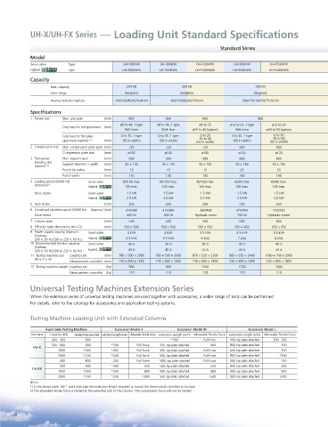
UH-X/UH-FX Series — Loading Unit Standard Specifications


                                                                                   Standard Series

            Model
            Servo valve    Type                UH-200kNX     UH-300kNX    UH-F300kNX    UH-500kNX    UH-F500kNX
            Hybrid  \EULG  Type               UH-200kNXh    UH-300kNXh    UH-F300kNXh   UH-500kNXh   UH-F500kNXh
                  \EULG
            Capacity
                    Max. capacity               200 kN               300 kN                     500 kN
                    Force range                Rangeless            Rangeless                  Rangeless
                    Analog indicator (option)  200/100/40/20/10/4 kN  300/150/60/30/15/6 kN  500/250/100/50/25/10 kN
            Specifications
            1.  Tensile test  Max. grip span   (mm)  800       800          800                  900
                                              ø8 to 40, 1 type  ø8 to 40, 1 type  ø8 to 25  ø12 to 50, 1 type  ø12 to 30
                        Grip face for rod specimens  (mm)
                                               With liner    With liner  ø25 to 40 (option)  With liner  ø30 to 50 (option)
                                                                                                       0 to 30
                        Grip face for flat plate   0 to 35, 1 type  0 to 35, 1 type  0 to 20  0 to 45, 1 type  30 to 50
                                                                           20 to 40
                        specimens (option)  *3    (mm)  (50 in width)  (50 in width)  (50 in width)  (60 in width)  (60 in width)
            2.  Compression test  Max. compression plate span  (mm)  720  720  720        800           800
                        Compression plate size   (mm)  ø100   ø100          ø100          ø120         ø120
            3.  Transverse/  Max. support span   (mm)  500     500          500           600           600
              bending test   Support diameter × width   (mm)  30 × 130  30 × 130  30 × 130  50 × 160  50 × 160
              (option)  *4
                        Punch tip radius   (mm)  15            15            15           25            25
                        Punch width     (mm)     130           130          130           160           160
            4.  Loading speed (50/60 Hz)   Servo valve  80/100 max.  80/100 max.  80/100 max.  65/80 max.  65/80 max.
              (mm/min) *1         Hybrid  \EULG  100 max.    100 max.      100 max.      100 max.     100 max.
                                       \EULG
               Drive motor        Servo valve   1.5 kW        1.5 kW       1.5 kW        1.5 kW        1.5 kW
                                  Hybrid  \EULG  2.0 kW       2.0 kW       2.0 kW        2.0 kW        2.0 kW
                                       \EULG
            5.  Ram stroke              (mm)     200           200          200           250           250
            6.  Crosshead elevation speed (50/60 Hz)  (Approx.) (mm)  315/380  315/380  380/450  375/450  210/250

               Drive motor                      400 W         400 W      Hydraulic motor  750 W      Hydraulic motor
            7.  Column span             (mm)     500           500          500           650           650
            8.  Effective table dimensions (W × D)  (mm)  500 × 500  500 × 500  500 × 500  650 × 650  650 × 650

            9.  Power supply capacity (Approx.)   Servo valve  4 kVA  4 kVA  5.5 kVA     4.5 kVA       5.5 kVA
              (3-phase,
                                       \EULG
              200 V, 50 Hz/200 to 220 V, 60 Hz)  Hybrid  \EULG  6.5 kVA  6.5 kVA  8 kVA  7 kVA         8 kVA
            10. Recommended breaker capacity  Servo valve  30 A  30 A       30 A          30 A         40 A
              (3-phase,
                                       \EULG
              200 V, 50 Hz/200 to 220 V, 60 Hz)  Hybrid  \EULG  40 A  40 A  50 A          40 A         50 A
            11. Testing machine size   Loading unit   (mm)  780 × 500 × 2000  780 × 500 × 2000  870 × 520 × 2300  960 × 650 × 2400  1060 × 700 × 2900
              (W × D × H)
                           Measurement controller  (mm)  740 × 800 × 1800  740 × 800 × 1800  740 × 800 × 1800  740 × 800 × 1800  740 × 800 × 1800
            12. Testing machine weight Loading unit   (kg)  900  900        1500          1700         2600
                           Measurement controller  (kg)  110   110          110           110           110
            Universal Testing Machines Extension Series
            When the extension series of universal testing machines are used together with accessories, a wider range of tests can be performed.
            For details, refer to the catalogs for accessories and application testing systems.

            Testing Machine Loading Unit with Extended Columns

                  Applicable Testing Machine  Extension Model S    Extension Model M         Extension Model L
            Series Name  Capacity (kN)  Standard Grip Span (mm) Extension Length (mm) Allowable Tensile Force  Extension Length (mm)  Allowable Tensile Force  Extension Length (mm)  Allowable Tensile Force
                    200 · 300    800                             *400        Full force  600, top plate attached  200 · 250
                    500 · 600    900      *300      Full force  500, top plate attached  400  800, top plate attached  300
             UH-X
                       1000     1000      *200      Full force  500, top plate attached  Full force  800, top plate attached  700
                       2000     1100      *200      Full force  500, top plate attached  Full force  800, top plate attached  1700
                       300       800       200      Full force  *400, top plate attached  Full force  600, top plate attached  150
                       500       900      *300         320  500, top plate attached  250  800, top plate attached  200
             UH-FX
                       1000     1000      *200         800  500, top plate attached  600  800, top plate attached  500
                       2000     1100      *200        1800  500, top plate attached  1500  800, top plate attached  1300
            NOTE:
            1) In the above table, the * mark indicates the extension length required to mount the thermostatic chamber or furnace.
            2) The allowable tensile force is limited at the extended part of the column. The compression force will not be limited.


      18