
Page 4 - Shimadzu MST-I
P. 4
Features
Test Examples
MST-I permits the strength testing of micro-components and monofilaments that were previously hard to test.
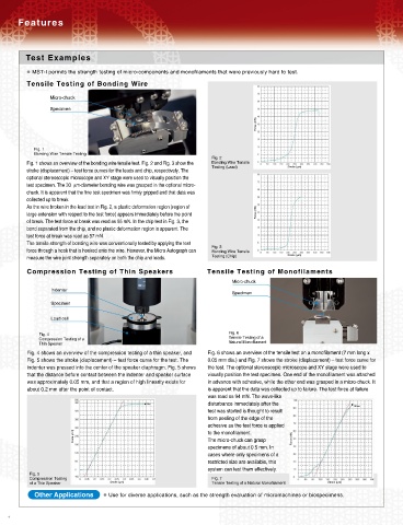
Tensile Testing of Bonding Wire
Micro-chuck
Specimen
Force (mN)
Fig. 1
Bonding Wire Tensile Testing
Fig. 2
Fig. 1 shows an overview of the bonding wire tensile test. Fig. 2 and Fig. 3 show the Bonding Wire Tensile
Testing (Lead) Stroke (μm)
stroke (displacement) – test force curves for the leads and chip, respectively. The
optional stereoscopic microscope and XY stage were used to visually position the
test specimen. The 30 μm-diameter bonding wire was grasped in the optional micro-
chuck. It is apparent that the fine test specimen was firmly gripped and that data was
collected up to break.
As the wire broken in the lead test in Fig. 2, a plastic deformation region (region of
large extension with respect to the test force) appears immediately before the point Force (mN)
of break. The test force at break was read as 55 mN. In the chip test in Fig. 3, the
bond separated from the chip, and no plastic deformation region is apparent. The
test force at break was read as 57 mN.
The tensile strength of bonding wire was conventionally tested by applying the test
Fig. 3
force through a hook that is hooked onto the wire. However, the Micro Autograph can Bonding Wire Tensile
measure the wire joint strength separately on both the chip and leads. Testing (Chip) Stroke (μm)
Compression Testing of Thin Speakers Tensile Testing of Monofilaments
Micro-chuck
Indenter
Specimen
Specimen
Load cell
Fig. 4 Fig. 6
Compression Testing of a Tensile Testing of a
Thin Speaker Natural Monofilament
Fig. 4 shows an overview of the compression testing of a thin speaker, and Fig. 6 shows an overview of the tensile test on a monofilament (7 mm long x
Fig. 5 shows the stroke (displacement) – test force curve for the test. The 0.05 mm dia.) and Fig. 7 shows the stroke (displacement) – test force curve for
indenter was pressed into the center of the speaker diaphragm. Fig. 5 shows the test. The optional stereoscopic microscope and XY stage were used to
that the distance before contact between the indenter and speaker surface visually position the test specimen. One end of the monofilament was attached
was approximately 0.05 mm, and that a region of high linearity exists for in advance with adhesive, while the other end was grasped in a micro-chuck. It
about 0.2 mm after the point of contact. is apparent that the data was collected up to failure. The test force at failure
was read as 94 mN. The wave-like
disturbance immediately after the
Brake
Brea
test was started is thought to result
from peeling of the edge of the
adhesive as the test force is applied
Force (mN) to the monofilament. Force (mN)
The micro-chuck can grasp
specimens of about 0.5 mm. In
cases where only specimens of a
restricted size are available, this
system can test them effectively.
Fig. 5
Compression Testing Fig. 7
of a Thin Speaker Stroke (μm) Tensile Testing of a Natural Monofilament Stroke (μm)
Other Applications Use for diverse applications, such as the strength evaluation of micromachines or biospecimens.
4