Page 10 - Shimadzu DUH-211/
P. 10

Specifications                                                                                                            Optional Accessories


             Model                                        DUH-211                          DUH-211S                                   Length Measurement Kit            BK7 (Glass Test Piece)  P/N 339-89207-14  Slender Specimen Holder  P/N 344-82943-40
                                                                                                                                      (Color or Monochrome)
             P/N                                     344-04250-XX (Windows 10)        344-04251-XX (Windows 10)                                                         Used to obtain the correction factors required for the   This attachment is used to firmly hold thin specimens
             Loading Unit  Loading Method      Electromagnetic coil                                                                   Length measurement kit, color:              P/N 347-24778-44        with an outer diameter of 0.15 mm to 1.6 mm, such as
                          Test Force Range     Full scale of 0.1 to 1,961 mN                                                          Length measurement kit, monochrome: P/N 347-24778-43  indenter when measuring the elastic modulus.  sewing machine needles, watch shafts, thin-shaped
                          Test Force Accuracy  ±19.6 µN or ±1% of displayed test force, whichever is greater                          Microscope images of the specimen surface can be
                          Minimum Measurement Increment  0.196 µN (for a test force not exceeding 1.96 mN)                            displayed on the PC screen. Measure the size of                     medical equipment, wires, sintered wires, and nonferrous
             Displacement  Measurement Method  Differential transformer                                                               indentations on the screen and save the images.   Triangular Pyramid Indenter   wires.
             Measurement Unit  Measurement Range  0 to 10 µm                                                                          Maximum magnification factor is ×2400 (when using a   with 100° Tip Angle
                          Minimum Measurement Increment  0.0001 µm                                                                    17″ monitor and an objective lens with a magnification    P/N 340-47011
                          Linearity            ±2% of full scale (20 µm)                                                              factor of 50). This accessory can be used with computers   This indenter, with a tip
             Indenter     Type                 Triangular pyramid indenter with tip angle of 115° (Vickers indenter and Knoop indenter are available as options.)  designated by Shimadzu.  angle of 100°, has a   Shape of indenter tip
                          Tip Radius           0.1 µm max.                                                                                                              smaller tip radius and
             Optical Monitor  Total Magnification (microscope)  ×500                                                                                                     makes smaller indentations   γ
                          Objective Lens       ×50 (Up to 2 lenses can be attached.)                                                                                    than an indenter with a tip   α  β
                          Eyepiece             ×10                                                                                                                                              α = β = γ = 100°
                          Lighting Method      Reflected illumination                                                                                                    angle of 115°. Used for
                          Light Source (lamp)  LED: 3 W, 3 V                                                                                                            testing small-size
                          Light-Path Switching  Observation or photograph (selectable)                                                                                  specimens.
             Micrometer   Collimation Method   Direct connection between encoder and control handle; synchronized movement of two indexes
                          Detector             Optical encoder
                          Effective Measurement Range  200 µm (with ×50 objective lens)                                                                                 Measurement Kit for Vickers Hardness  Disk-Type Vacuum Suction Unit
                          Minimum Measurement Increment  0.01 µm/pulse                                                                                                                       P/N 347-24449-01                  P/N 344-86201-42
             Specimen Stage  Vertical Distance  Approx. 60 mm                                                                                                           (Contents: Vickers Indenter 1 pc, Inspection Report 1 pc)  Used for 5″, 6″, and 8″ wafers.
                          Area                 Approx. 125 (W) × 125 (L) mm                                                                                             The verification in accordance with standard (ISO   (Air supply for suction must be separately prepared.)
                          Stage Movement Range  25 mm in both X and Y directions                                                      Objective Lens                    6507-2) is done at the factory.
                          Specimen Holder      Specimen dimensions (i.e., 8 (thickness) × 30 (width) mm) when thin-type attachment (type 3) is used                     Factory verified for compliance with Vickers hardness
             Test Modes   Load–Hold Test                                                                                              ×100 objective lens P/N 344-89977-40  test standards.               Micrometer Head (Digital Display)
                          Load–Unload Test                                                                                            ×40   objective lens P/N 347-25400  Please order simultaneously with the DUH.        P/N 347-25447-12 (2 unit)
                          Cyclic Test                                                                                                 ×20   objective lens P/N 344-89924-40                               Used to digitally display the amount of stage movement
                          Depth Setting Test                                                                                          ×10   objective lens P/N 344-89941-40                               (up to a maximum of 25 mm) in the front/back or
                          Depth Setting Load–Unload Test                                                                              ×40   objective lens with ultra-long operating distance  Measurement Kit for Knoop Hardness
                          Step Load Test                                                                                                                             P/N 344-89300-41        P/N 347-24449-11  left/right directions in 1 µm increments. (Photo shows
                          Step Load-Unload Test                                                                                       40× objective lens with ultra-long operating distance.              this head attached to a stage.)
             Required PC  OS                   Windows  10 Pro (64 bit edition)                                                       Improves contrast in the field-of-view.  (Contents: Knoop Indenter 1 pc, Inspection Report 1 pc)
                                                    ®
             Specifications  Disk Drives        CD-ROM drive                                                                                                             The verification in accordance with standard (ISO
                          Expansion Bus        PCI Express ×1 (full-length), 2 slots min. more than one ×1 slot is reguired (or slot size ×2 or more)                   4545-2) is done at the factory.
             Utilities    Power Supply         Single phase, AC 100–115 V ± 10%, AC 230 V ± 10% (Ground resistance 100   max.)                                          Factory verified for compliance with Vickers hardness
                          Power Consumption    Approx. 100 W (not including power consumption of PC)                                  Windbreak                         test standards.
                          Grounding            The ground terminal on 3-prong connectors must be properly grounded with grounding resistance at 100   or less.  P/N 347-24400-01  Please order simultaneously with the DUH.
                          Temperature          Recommended temperature: 23±1°C                                                        This case minimizes the influence of air disturbances,
                                               Allowable range: 10°C to 35°C                                                          such as due to DUH tester exposure to air flow or sound.
                          Vibration            Horizontal vibration: 0.017 Gal max. (at 10 Hz or more), 0.01 µm max. (at less than 10 Hz)  W700 × D650 × H750 (mm)      Desk-Type Vibration Absorbing Bench
                                               Vertical vibration:      0.010 Gal max. (at 10 Hz or more), 0.005 µm max. (at less than 10 Hz)                                                P/N 344-04193-06
                          Humidity             80% max. (no condensation)                                                                                               This bench with desk-type coil springs is recommended
             Dimensions and  External Dimensions  Tester:           Approx. 355 (W) × 405 (D) × 530 (H) mm                            Windbreak (Large type)            if the DUH-211/211S tester is used in areas that are
             Weight                            Control unit: Approx. 315 (W) × 375 (D) × 110 (H) mm                                                         P/N 347-24400-02  subject to strong vibrations.
                          Weight               Tester:           Approx. 60 kg                                                        In the case that Active Vibration-Absorbing Bench is used           Rotation Stage
                                               Control unit: Approx. 5 kg                                                             this is select.                                                                          P/N 344-82857-01
                                                                                                                                      W700 × D650 × H950 (mm)           Active Vibration-Absorbing Bench  This stage has a diameter of 125 mm and can rotate in
                                                                                                                                                                                       P/N 344-04211-11: AC 120 V  the range ±5°.
                                                                                                                                                                                       P/N 344-04211-12: AC 230 V
                                                                                                                                      Vickers Hardness Standard Block   This bench is used together with a special mount and
                                                                                                                                                            P/N 340-06619-07  performs active vibration absorption over a wide range,   Objective Micrometer
                                                                                                                                      Used for measuring hardness with the 700HMV micro   from 0.7 Hz to 100 Hz.               P/N 046-60201-02
                                                                                                                                      Vickers. Used as a rough guide for Vickers hardness                 Used to adjust the microscope's magnification factor.
                                                                                                                                      measurement.                                                        Marked with scale graduations at 10 µm intervals.
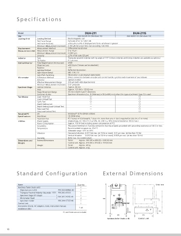
            Standard Configuration                                    External Dimensions


                                                                                                                                       Installation Precautions Consider the following points when deciding on the installation location of the tester.
             Name                                    Quantity                                             Unit: mm
             Hardness Tester (main unit)               1                                                                               1. To minimize vibration:        2. To minimize air drafts and sounds:  3. To ensure testing accuracy:
                 Objective Lens (×50)   P/N 344-89964-40  1                                                                            1) Install the tester in a location where floor   1) Do not install the tester in locations that are   Be especially careful when performing the following
                 Triangular Pyramid Indenter (tip angle: 115°)  P/N 340-47013  1                                                         vibration is minimal. Normally, place the tester on   directly or indirectly subject to streams of air from   types of tests:
                                                                                                                                                                                                         • Tests involving test forces of 1 mN or less
                                                                                                                                                                          air-conditioning equipment.
                                                                                                                                         a vibration-absorbing bench.
                 Specimen Stage (XY stage)  )          1                                                                               2) Do not install the tester in a location where   2) Use a windbreak during testing.  • Tests involving the measurement of changes for
                 Micrometer Head        P/N 347-24205-41  2           530                                                                people requently walk by.      3) Do not open or close nearby doors during testing.     indentation depths of 0.05 µm or less
                 Specimen Holder        P/N 344-17737-40  1                                            PC                              3) Do not install the tester near equipment that   4) Do not install the tester near sound-generating   In these cases, be sure to maintain the following
             Control Unit                              1                                                                                 generates vibrations.              equipment (e.g., telephones).  conditions:
             Accessories (Cords, AC adapters, tools, instruction manual,                                                               4) If possible, install the tester on the first floor of a          • Temperature: No fluctuations greater than ±1°C.
                                                                                                                                         building.
                                                                                                                                                                                                         • Vibration: Refer to specification table.
             installation disk)                       1 set                                                                            5) Install the tester as far away as possible from
                                            PC and Printer are not included.                                110                          streets, roads and railway tracks.
                                                                                355              315                                   6) Do not perform testing if vibration-generating
                                                                                                                                         equipment (e.g., a crane) is being used nearby.
                                                                         Hardness tester (main unit)  Control unit
                                                                                                                                                                                                                       DUH-211/211S
      10                                                                                                                                                                                                                 Dynamic Ultra Micro Hardness Testers  11
   5   6   7   8   9   10   11   12