
Page 22 - Shimadzu Journal vol.10 Issue1
P. 22
Materials Science
1 2
Fluoroscopy of the Cylindrical LIB Positive current
collector tab
Fig. 2 shows a fluoroscopic image of a 21700* type LIB cell. The
2
contrast in a fluoroscopic image is determined by the relative dif-
ference of X-ray absorption of the materials. Fluoroscopy is used
for simple inspection because it can be observed in short time. As
shown in Fig. 3, electrodes are composed of cathodes, anodes, and 1
separators, which are arranged alternately.
*2 Battery model diameter : 21 mm, full length : 70 mm
2
Fig. 4 Cross-Sectional Image of the 21700 LIB Cell
Anode
Cathode
Separator
Fig. 2 Fluoroscopic Image of the Positive Fig. 3 Schematic Diagram of
Terminal in a 21700 Type LIB Cell the Electrode Structure in a LIB
Negative
current
collector tab
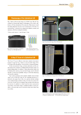
X-Ray CT Scan of a Cylindrical LIB
The X-ray CT scan is effective when more detailed observation/
analysis is required. Fig. 4 shows a cross-sectional image of the
21700 type LIB cell, and Fig. 5 shows its three-dimensional image.
In the cross-sectional image, cathodes and anodes and the cur-
rent collector tab, which are overlapped in fluoroscopic images, are
clearly distinguished. In addition, a three-dimensional image can
be displayed by stacking cross-sectional images, and the internal
structure is observed by partially cutting or selectively displaying
only specific materials.
Fig. 6 shows an image of the unrolled cylinder cross-sectional Fig. 5 Three-Dimensional Image of the 21700 LIB Cell
image of the 21700 type LIB cell. The unrolling position is in-
dicated by the purple line in Fig. 6-A, and the unrolled cylinder
cross-sectional image is shown in Fig. 6-B. Here, the current col- A B
lector tab is shown, and by enlarging it the structure of its joint can Negative current
be observed. In addition to vertical and horizontal cross-section collector tab
observation, observation along a cylindrical surface is also pos-
sible, so, the electrodes can be observed as they were before they Joint of
were rolled. negative current
collector tab
Fig. 6 Unrolled Cylinder Cross-Sectional Image of the 21700 LIB Cell
-A Indicates unrolling position -B Unrolled cross-sectional image
Shimadzu Journal vol.10 Issue1 21