
Page 9 - Shimadzu Dynamic and Fatigue Testing Systems
P. 9
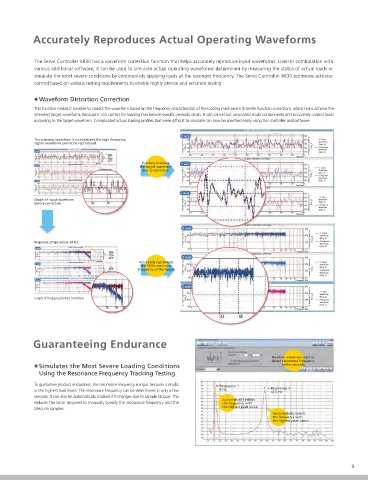
Accurately Reproduces Actual Operating Waveforms


            The Servo Controller 4830 has a waveform correction function that helps accurately reproduce input waveforms. Used in combination with
            various additional software, it can be used to simulate actual operating waveforms determined by measuring the status of actual loads or
 Evaluate   simulate the most severe conditions by continuously applying loads at the resonant frequency. The Servo Controller 4830 optimizes actuator
            control based on various testing requirements to enable highly precise and accurate testing.
 Product Endurance in
 Any Manner Desired  Waveform Distortion Correction
            This function makes it possible to correct the waveform based on the frequency characteristics of the loading mechanism (transfer function correction), which helps achieve the
            intended target waveform. Because it can correct for loading mechanism-specific periodic strain, it can cancel out unwanted strain components and accurately control loads
            according to the target waveform. Complicated actual loading profiles that were difficult to simulate can now be specified easily using this controller and software.
 Endurance testing requires a wide variety of testing inputs in order to evaluate the reliability of products or assemblies or to verify design
                                                                                  Graph1: Distortion Correction
 specifications. Shimadzu's light-weight and compact hydraulic actuators can be installed on a wide variety of stands and used to generate test
                                                             X axis
 inputs that closely approximate the conditions under which samples are used. Therefore, they satisfy a wide variety of testing requirements, such   The response waveform is rounded and the high-frequency   X-Target
            region waveform cannot be reproduced.                                                          Waveform
                                                                                                           (Disp_X)
 as for actuator installation, loading mechanism design, multi-axis synchronized actuator testing, and multi-sample batch testing.  X-Target Waveform  (Disp_X)  X-Response Waveform  (Disp_X)  X-Response
                        Graph1: Distortion Correction                                                      Waveform
            X axis                   X-Target                                                              (Disp_X)
                                     Waveform
 Two-Degree-of-Freedom PID Control Minimizes Effects from External Disturbances  X-Target Waveform  (Disp_X)  Time (sec)  X-Response Waveform  (Disp_X)  (Disp_X)  Precisely matches   Y axis  Graph2: Distortion Correction  Time (sec)
                                     X-Response
                                     Waveform
                                     (Disp_X)
            Y axis      Graph2: Distortion Correction  the target waveform
 The control method (two-degree-of-freedom PID control) is able to optimize the target response for specified signals and the response to external noise. Optimizing the control   Y-Target Waveform  (Disp_Y)  Y-Response Waveform  (Disp_Y)  Y-Target   due to correction.  Y-Response Waveform  (Disp_Y)  Y-Target
                                                                                                           Waveform
                                     Waveform
                                                                                                           (Disp_Y)
                                     (Disp_Y)
                                     Y-Response
 parameters using the autotuning feature helps maximize the system performance. The 24-bit high-resolution measurement function and 10 kHz high-speed feedback ensure   Waveform   Y-Target Waveform  (Disp_Y)  Y-Response
                                     (Disp_Y)
                                 Time (sec)                                                                Waveform
                        Graph3: Distortion Correction                                                      (Disp_Y)
 that even sharp changes in test force or stroke can be controlled reliably.  Z axis  Z-Target     Time (sec)
             Z-Target Waveform  (Disp_Z)  Z-Response Waveform  (Disp_Z)  Waveform  Graph3: Distortion Correction
                                     (Disp_Z)
                                     Z-Response
                                     Waveform
 Light                           Time (sec)  (Disp_Z)        Z axis
 Compact    Graph of input waveform                                                                        Z-Target
                                                                                                           Waveform
 Long Stroke  before correction                               Z-Target Waveform  (Disp_Z)               Z-Response Waveform  (Disp_Z)  (Disp_Z)
                                                                                                           Z-Response
                                                                                                           Waveform
                                                                                                   Time (sec)  (Disp_Z)
                                                                                  Graph1: Distortion Correction
                                                             X axis
                                                                                                           Waveform
 With vertical and                                            X-Target Waveform  (Disp_X)               X-Response Waveform  (Disp_X)  X-Target
                                                                                                           (Disp_X)
 With a trunnion bracket  left/right rotation mechanisms  Response drops above 30 Hz.                      X-Response
 Portable torsional actuator                                                                               Waveform
                        Graph1: Distortion Correction                                                      (Disp_X)
             X axis
 With vertical movement and   XYZ 3-axis loading frame  X-Target                                   Frequency (Hz)
                                     Waveform
 left/right rotation mechanisms  X-Target Waveform  (Disp_X)  X-Response Waveform  (Disp_X)  (Disp_X)  Y axis  Graph2: Distortion Correction
                                     X-Response
                                     Waveform
                                     (Disp_X)
                                 Frequency (Hz)  Accurately reproduces
                        Graph2: Distortion Correction                                                      Y-Target
             Y axis                  Y-Target   the 50 Hz maximum                                          Waveform
             Y-Target Waveform  (Disp_Y)  Y-Response Waveform  (Disp_Y)  Waveform  frequency of the target.  Y-Target Waveform  (Disp_Y)  Y-Response Waveform  (Disp_Y)  (Disp_Y)
                                     (Disp_Y)
                                                                                                           Y-Response
 For example ...                     Waveform                                                              Waveform
                                     Y-Response
                                     (Disp_Y)
                                 Frequency (Hz)                                                            (Disp_Y)
                        Graph3: Distortion Correction
             Z axis                                                                                Frequency (Hz)
 The riding comfort of automobiles is directly related to reducing the amount of   Z-Response Waveform  (Disp_Z)  Z-Target   Graph3: Distortion Correction
                                     Waveform
                                     (Disp_Z)
 vibration and noise. Synchronizing multiple actuators using the Servo Controller 4830   Z-Target Waveform  (Disp_Z)  Z-Response  Z axis
                                     Waveform
                                     (Disp_Z)
                                 Frequency (Hz)                                                            Z-Target
 allows accurately simulating the dynamic waveform experienced by parts and                                Waveform
            Graph of frequency before correction              Z-Target Waveform  (Disp_Z)               Z-Response Waveform  (Disp_Z)  (Disp_Z)
 components during actual travel.                                                                          Z-Response
                                                                                                           Waveform
                                                                                                           (Disp_Z)
                                                                                                   Frequency (Hz)
 Horizontal   Vertical   Torsional
 actuator  actuator   actuator
 Operating PC software
 Sample (rubber bush)  Torque detector  Servo valve
 Bearing  Torque signal  Guaranteeing Endurance
 Servo valve
 Test force signal
 Driving signal   Displacement signal                                                      Random waves are used to
 Displacement signal                                                                       detect resonance frequency
 Driving signal  Simulates the Most Severe Loading Conditions                                 within seconds.
 Servo Controller 4830
 Horizontal   Torque   Using the Resonance Frequency Tracking Testing
 actuator  actuator  Driving signal
 This allows users to perform 3-axis endurance tests   (2)  (1)  Angle signal  To guarantee product endurance, the resonance frequency is input because it results
 with forces in axial and torsional directions to evaluate   Servo Controller 4830  Resonance 1  Resonance 2
                                                                          6 Hz
 Test force signal  in the highest load levels. The resonance frequency can be determined in only a few   47.5 Hz
 the endurance of rubber bushings, which are exposed   seconds. It can also be automatically tracked if it changes due to sample fatigue. This
 to forces in various directions. The interference   reduces the labor required to manually specify the resonance frequency and the   Automatically selects
                                                                           the frequency with
 correction function permits tests using waveforms that   Servo valve  Driving signal  the highest peak value.
 Force detector  stress on samples.
 are even closer to target waveforms.  (3)Vertical actuator  Displacement signal           Automatically selects
 Servo Controller 4830                                                                     the frequency with
                                                                                           the highest peak value.
 Note: The interference correction function corrects for interference in
 other directions that result from dynamic loads. In various types of
 tests, it sends command signals for the opposite phase as the
 interference components and cancels out interference components,   Test frame
 which achieves a waveform that more closely resembles the target   Accumulator  Hydraulic power
 waveform.  supply unit
 8                                                                                                                   9