
Page 9 - Shimadzu Xctal 5000
P. 9
Applications
(Absorption, Dark-field, and Phase Images)
CFRP Laminate Layers Plastic Bottles
This is a sample scan of a material in which the angle of a prepreg of fibers aligned along one direction is changed to This is a sample scan of a plastic spray bottle. With a phase image, it is possible to observe the voids in the plastic,
build up the laminate layers. It is evident from the cross-sectional images that there are three orientation directions, without the impact of artifacts due to a spring. In addition, the internal structure of the sample where different types
and from the VR image, these have evidently been used by turns in the laminate. of plastic are joined can be observed using absorption and phase images due to the difference in the absorption
coefficients and densities.
0° direction 45° direction -45° direction
Vector Direction Color Maps (CT) VR Image (Vector Direction Color Map)
Cross-Sectional Image Cross-Sectional Image Cross-Sectional Image Cross-Sectional Image
CFRP Cloth Material (Absorption) (Phase) (Absorption) (Phase)
This is an example of the analysis of fiber orientations in a laminate material, woven with carbon fibers.
Tomatoes
This is a sample scan of a tomato. The internal structure of the vegetable can be observed even if there is a high
moisture content.
Vector Direction Color Maps (CT) VR Image (Vector Direction Color Map)
CFRP Random Laminate
Cross-Sectional Image (Dark) Cross-Sectional Image (Dark) VR Image (Dark)
This is a sample scan of a material in which pieces of carbon tape with random orientations are used to build up the
laminate layers. X-rays scattered along the orientation of the grating are detected, enabling the fibers oriented along
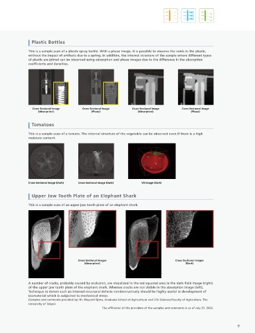
these directions to be detected. Upper Jaw Tooth Plate of an Elephant Shark
This is a sample scan of an upper jaw tooth plate of an elephant shark.
0° direction 45° direction 90° direction -45° direction
Cross-Sectional Images (Dark)
Cross-Sectional Images Cross-Sectional Images
(Absorption) (Dark)
Fiber orientation analysis
1.5mm 1.5mm
A number of cracks, probably caused by occlusion, are visualized in the red squared area in the dark-field image (right)
Vector Direction Color Map (CT) 7mm Cross-Sectional Image of the Enlarged Absorption Image of the Area of the upper jaw tooth plate of the elephant shark. Whereas cracks are not visible in the absorption image (left).
in the Yellow Frame, and the Results of an Orientation Analysis
FOV : 40 mm (Image obtained with the inspeXio SMX-225CT FPD HR Plus) Technique to detect such an internal structural defects nondestructively should be highly useful in development of
biomaterial which is subjected to mechanical stress.
With the random sheet of chopped tape, variation of the fiber orientation changes the mechanical properties and (Samples and comments provided by: Dr. Mayumi Iijima, Graduate School of Agricultural and Life Sciences/Faculty of Agriculture, The
moldability, thereby changing the quality of the molded product. The fiber orientation analysis makes it possible to University of Tokyo)
predict the quality nondestructively, and further, enables research into the design of laminates with a slight variation The affiliation of the providers of the samples and comments is as of July 27, 2022.
and stable quality.
(Samples and comments provided by: ICC, Kanazawa Institute of Technology)
8 9