Page 4 - Shimadzu Xctal 5000
P. 4

Both Wide Field of View and
                     Detailed Structural Observations                                                                                   Applications (Dark-field Images)


                     Detailed Structural Observations                                                                                     GFRP Injection Molded Items

                                                                                                                                        In injection molding, molding defects can occur when a linear mark (weld line) forms where the molten resins meet.
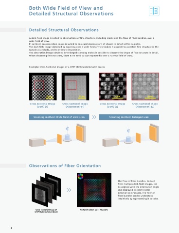
                     A dark-field image is suited to observations of fine structure, including cracks and the flow of fiber bundles, over a   With this system, dark-field images can be obtained while changing the angle of the sample, so the fiber flow can be
                     wide field of view.                                                                                                 analyzed, enabling the position of weld lines to be specified.
                     In contrast, an absorption image is suited to enlarged observations of shapes in detail within samples.
                     The dark-field image obtained by scanning over a wide field of view makes it possible to ascertain fine structure in the
                     sample as a whole, and to estimate its position.
                     The absorption image obtained by enlarged scanning makes it possible to observe the shape of fine structure in detail.
                     When observing fine structure, there is no need to scan repeatedly over a narrow field of view.


                     Example: Cross-Sectional Images of a CFRP Cloth Material with Cracks                                                                  0° direction    45° direction    90° direction   -45° direction

                                                                                                                                                                Fiber Orientation Analysis from Four Data Samples


                                                                                                                                                                 Weld line

                                 10 mm                 10 mm                   5 mm                   5 mm


                     Cross-Sectional Image  Cross-Sectional Image    Cross-Sectional Image  Cross-Sectional Image
                          (Dark) (1)          (Absorption) (1)            (Dark) (2)         (Absorption) (2)


                        Scanning method: Wide field of view scan            Scanning method: Enlarged scan
                                                                                                                                                                             7mm                              2mm

                                                                                                                                                          Vector Direction Color Map (CT)  Results of an Absorption Orientation Analysis
                                                                                                                                                                                           (Image obtained with the inspeXio
                                                                                                                                                                                               SMX-225CT FPD HR Plus)
                                                                                                                                                          In comparison to conventional X-ray CT systems, the position of
                                                                                                                                                            the weld line can be specified across a wider field of view.


                                                                                                                                          Biocoke

                                                                                                                                        Biocoke is a solid biofuel formed from plants through photosynthesis. In this example, fine cracks produced during
                                                                                                                                        formation can be visualized using dark-field images. Fine cracks invisible with conventional X-ray CT can be visualized
                                                                                                                                        by detecting the scattering of X-rays at the borderline between the material and the crack (air).
                     Observations of Fiber Orientation


                                                                                 The flow of fiber bundles, derived
                                                                                 from multiple dark-field images, can
                                                                                 be aligned with the orientation angle                                                                                                    Crack
                                                                                 and displayed in color (vector
                                                                                 direction color maps). The flow of                      Cross-Sectional Image (Absorption)  Cross-Sectional Image (Dark)       VR Image (Dark)
                                                                                 fiber bundles can be understood
                                                                                 intuitively by representing it in color.
                                                                                                                                        The quantitative analysis of microscopic cracks using this system has become a standard evaluation to check whether
                                                                                                                                        the combustion properties of biocoke are as close as possible to those of coal coke, thus laying the foundations for
                                                                                                                                        achieving a carbon neutral society through conversion to renewable energy.
                         Cross-Sectional Image of       Vector Direction Color Map (CT)                                                 (Samples and comments provided by: Professor Tamio Ida of the Bio-Coke Research Institute, Kindai University)
                         CFRP Cloth Material (Dark)
                                                                                                                                                                            The affiliation of the providers of the samples and comments is as of July 27, 2022.


        4                                                                                                                                                                                                                                    5
   1   2   3   4   5   6   7   8   9