
Page 7 - Shimadzu MALDImini-1
P. 7
The Technology Behind MALDImini-1
Compact design with unique ion optics system and layout MALDImini Console
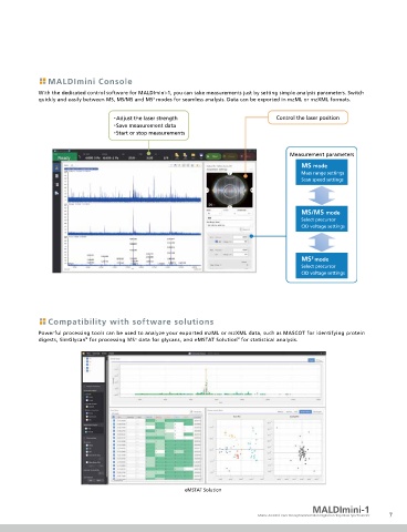
The laser optic system, sample stage, and vacuum exhaust system have all been nely optimized to reduce the size of the device. With the dedicated control software for MALDImini-1, you can take measurements just by setting simple analysis parameters. Switch
3
quickly and easily between MS, MS/MS and MS modes for seamless analysis. Data can be exported in mzML or mzXML formats.
Laser
・Adjust the laser strength Control the laser position
・Save measurement data
・Start or stop measurements
Ion trap Quadrupole de ector
Measurement parameters
MS mode
Mass range settings
Scan speed settings
Detector Sample plate
MS/MS mode
Select precursor
CID voltage settings
Ion and laser optics steer the laser beam to hit the sample orthogonally to the plate,
enabling high ion transmittance and a more compact layout. Following ionization,
the beam is de ected 90° to ensure maximum transfer of ions to the ion trap. 3
MS mode
Select precursor
CID voltage settings
Digital Ion Trap (DIT) technology provides high sensitivity over a
wide mass range, despite the device's small footprint
The world- rst* Digital Ion Trap (DIT) technology, unique to Shimadzu, uses rectangular wave RF to trap ions rather than the sine Compatibility with software solutions
wave RF which has been used in ion-trapping devices until now.
Powerful processing tools can be used to analyze your exported mzML or mzXML data, such as MASCOT for identifying protein
digests, SimGlycan for processing MS data for glycans, and eMSTAT Solution for statistical analysis.
n
™
™
Smaller electronics make it possible to trap Driving waveform in a
ions in a higher mass range conventional ion trap
Driving waveform in the DIT
To adjust the voltage, a large high
High voltage voltage power supply and a coil to
DC supply produce sine wave RF are required.
RF switch A large high voltage power supply is not required to
adjust the frequency.
DIT layout Because a frequency scan is used as the mass separation method, it is
possible to make MS/MS and even MS measurements with a device far
3
smaller than one using a Triple Q or TOF/TOF con guration.
*As of May 2019, from internal research eMSTAT Solution
MALDImini-1
6 Matrix-Assisted Laser Desorption/Ionization Digital Ion Trap Mass Spectrometer 7