
Page 11 - Shimadzu NJ-SERVO
P. 11
Even More Expandability Thanks to the Software Specifications
—Capable of More Complicated Control and Model Dynamic NJ-1kNV-100 NJ-5kNV-100 NJ-10kNV-100 NJ-20kNV-100 NJ-30kNV-100
±5 kN
±1 kN
±20 kN
±30 kN
±10 kN
Storage of Test Results Thanks to a Variety of Software Programs— Test Force Static ±1 kN ±5 kN ±10 kN ±20 kN ±30 kN
±100 mm
Stroke (Full stroke) (200 mm)
Single wave: 20 cm/sec (loaded); Single wave: 72 cm/sec (loaded); Single wave: 40 cm/sec (loaded);
Max. Speed
Continuous: 15 cm/sec (loaded, sine wave) Continuous: 50 cm/sec (loaded, sine wave) Continuous: 30 cm/sec (loaded, sine wave)
Sensor Indicator Test Force ±0.5% indicated value, or ±0.02% of the load cell rating, whichever is larger
Accuracy Stroke ±1% indicated value, or ±0.1% of the rating, whichever is larger
Fatigue and Static Characteristics Programed Combination Static Testing Frequency-Sweep Testing Multi-Axis Combination Multi-Axis Working L0 980 mm 1080 mm 1260 mm 1385 mm 1550 mm
Endurance Testing Testing Testing Testing Resonance Frequency Sine Wave Testing Waveform Simulation Actuator 680 mm 730 mm 750 mm 840 mm 820 mm
Tracking Testing Testing Unit Size L1
L2 130 mm 140 mm 140 mm
Servo W×H×D 700×715×552 mm 700×1250×350 mm
Amplifier Size
Fatigue and Endurance Tests and Static Characteristics Tests (Standard Software) Weight Approx. 30 kg Approx. 70 kg Approx. 110 kg Approx. 180 kg Approx. 220 kg
Displacement control 10 Hz, Test force (kN) 3-phase 200 V, 7 kVA 3-phase 200 V, 12 kVA 3-phase 200 V, 18 kVA 3-phase 200 V, 23 kVA
The standard software provides support -50 test force target: 250% Displacement (mm) Power Requirements Single-phase 100V 1.5kVA Single-phase 100V 1.5kVA Single-phase 100V 1.5kVA Single-phase 100V 1.5kVA
Compatible Controllers
Servo Controller 4830
for general-purpose endurance tests, -0 Time (sec) -120 Amplitude Characteristics See amplitude characteristics diagrams.
including routine endurance tests with Push Tests -50 0 0.05 0.1 0.15 0.2 -80 Each system is adaptable for longer stroke/higher speed.
peak values specified, as well as tests of You can apply a constant load to the Test Force (N) FS:5000 N -100 -40 Displacement (mm) FS:150 mm
rubber and springs combining static test object regardless of its degree of -150 0.0
wear.
-40
-200
characteristics tests and endurance tests. -250 -80 Appearance of the Unit
The system enables testing in which loads -300 -120
(test force targets) and zero loads are Loading up to a set test force Removing the piston (zero loading) Displacement gauge (DTF) Trunnion shaft Servo motor
repeatedly impressed on a test sample,
which was difficult to date.
L2
L1
L0
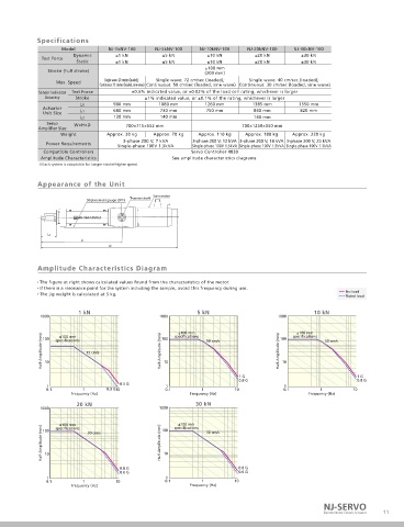
Frequency-Sweep Tests and Resonant Frequency Tracking Tests Frequency-Sweep Tests Amplitude Characteristics Diagram
The figure at right shows calculated values found from the characteristics of the motor.
Resonant frequency endurance tests, in which particularly harsh vibrations are If there is a resonance point for the system including the sample, avoid this frequency during use.
applied to the sample, and frequency-sweep tests, which evaluate frequency The jig weight is calculated at 5 kg. No load
Rated load
characteristics, are indispensable tests for product warranties and product
performance evaluations.
Using the 4830 software, resonant frequency transitions during testing are 1000 1 kN 1000 5 kN 1000 10 kN
detected in just a few seconds. The frequency is corrected to the resonant
frequency to match the state of the test sample. 100 specifications 100 specifications 100 specifications
±100 mm
±100 mm
Half-Amplitude (mm) 15 cm/s Half-Amplitude (mm) Half-Amplitude (mm)
±100 mm
Multi-Axis Working Waveform Simulation Tests 50 cm/s 50 cm/s
Synchronized actuator control is enabled for up to four units. To start the 10 10 10
test, just read in vibration waveforms, obtained from actual work, in CSV 1 G 1 G
format. Difficult parameter settings are configured automatically. 0.8 G 0.8 G
1 0.5 G 1 1
Enlarged 0.1 1 0.3 G 10 0.1 1 10 0.1 1 10
Working Waveform Simulation Test Frequency (Hz) Frequency (Hz) Frequency (Hz)
(1 axis, test stroke control) 1
20 kN 30 kN
1000 1000
Time Series Chart
±100 mm ±100 mm
Half-Amplitude (mm) Half-Amplitude (mm)
Every detail has been faithfully reproduced. 100 specifications 100 specifications
Error margin wave (target wave - response wave) 30 cm/s 30 cm/s
is almost 0.
Frequency Components Chart 10 10
0.8 G 0.8 G
0.6 G 0.6 G
1 1
0.1 1 10 0.1 1 10
50 Hz up to has been faithfully reproduced. Frequency (Hz) Frequency (Hz)
NJ-SERVO
10 Electric Motor Driven Actuator 11